7. Connection Diagram
Oki Data CONFIDENTIAL
44983601TH Rev.1
7-15 /
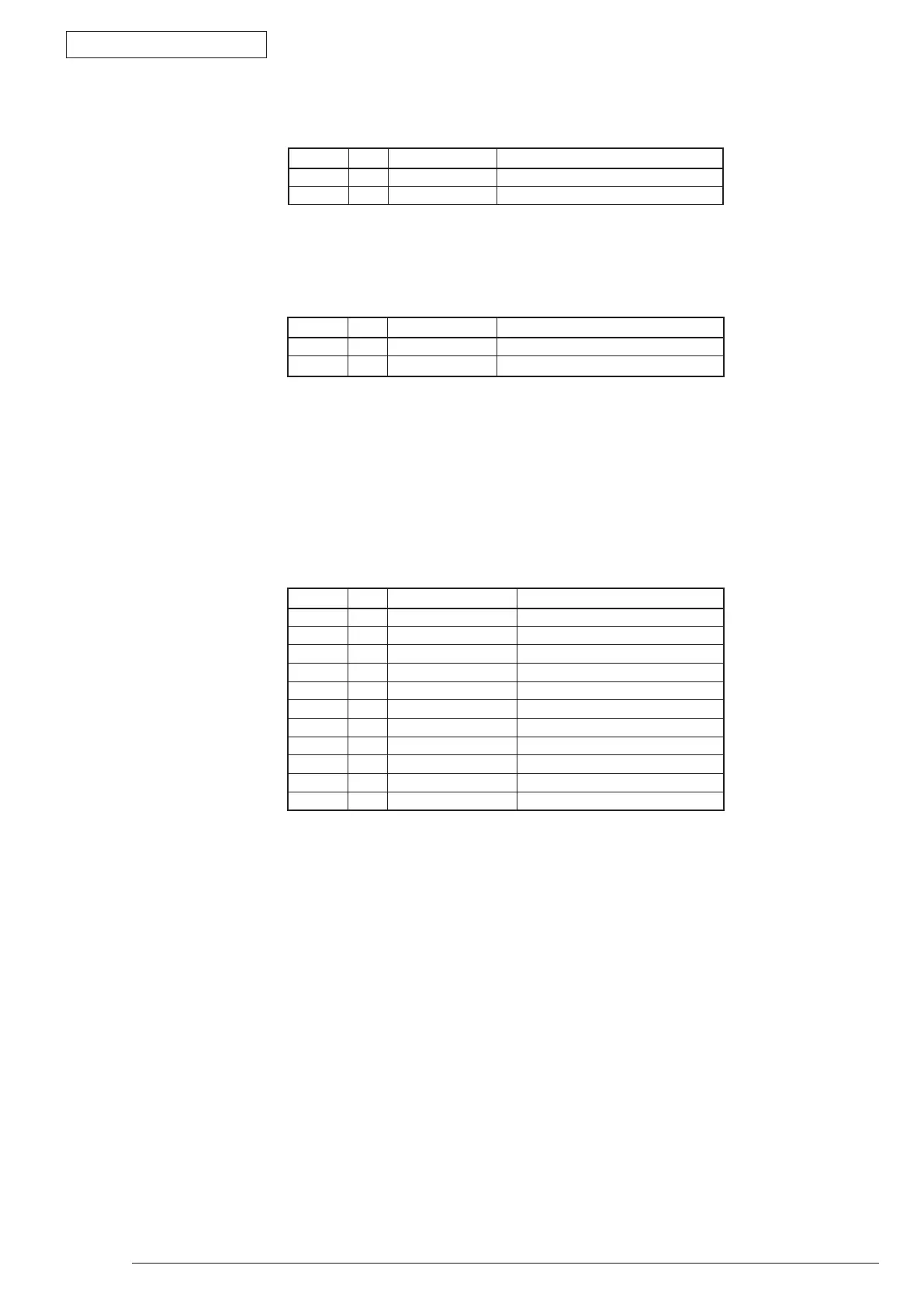
PinNo. I/O Signal Function
1 I AC(LIVE) ACinput
2 I AC(NEUTRAL) ACinput
• CN101ConnectorPinAllocation
(ConnectiontotheACSWAssy)
• CN2ConnectorPinAllocation
(ConnectiontotheFuserUnit)
• CN3ConnectorPinAllocation
(Connection to the Main Control Board)
PinNo. I/O Signal Function
1 O AC(NEUTRAL) ACoutput
2 O AC(LIVE) ACoutput
PinNo. I/O Signal Function
1 O +24V Motor/FAN/ClutchDrivePower
2 O +24V Motor/FAN/ClutchDrivePower
3 C GND Ground
4 C GND Ground
5 O ACZEROX-P ACZeroCross
6 C GND Ground
7 C GND Ground
8 O +5V LogicCircuitPowerSupply
9 O +5V LogicCircuitPowerSupply
10 I HEATON-N HeaterON
11 I HARDGUARD-N Hard Guard