EasyManuals Logo

Oki C911 Disassembly & Reassembly Procedures

Oki C911
40 pages
To Next Page IconTo Next Page
To Previous Page IconTo Previous Page
Page #12 background imageLoading...
Page #12 background image
10
24
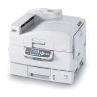
Remove the photo interrupter sensor from
the job offset assembly. It is clipped in with
3 tabs.
25
Unthread the photo interrupter sensor wiring harness and let hang over the rear of the printer.
26
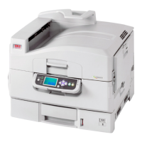
Remove 3 screws securing the job offset
into the printer. 1 short screw on the top
frame and 2 longer screws into the base
frame – 1 in the rear and 1 in the front.
(Front screw is shown on next page)

Other manuals for Oki C911

Questions and Answers:

Question and Answer IconNeed help?

Do you have a question about the Oki C911 and is the answer not in the manual?

Oki C911 Specifications

General IconGeneral
BrandOki
ModelC911
CategoryPrinter
LanguageEnglish

Related product manuals