Do you have a question about the Oki C9850 and is the answer not in the manual?
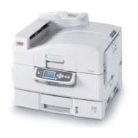
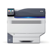
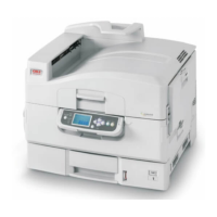
Overview of the printer's system configuration and components.
Details the main internal parts of the printer.
Lists and illustrates optional components available for the printer.
Lists technical specifications including dimensions, weight, speed, resolution, temperature, and humidity.
Details USB, Network, and Parallel interface specifications.
Details the block diagram and components of the main control PCB.
Illustrates the block diagram of the Engine Control PCB.
Describes the low and high voltage power units.
Overview of the electrophotographic printing process steps.
Details the paper path and movement through the printer.
Details sensors that detect paper presence, position, and stacker status.
Lists and describes other sensors like toner, thermal, and humidity sensors.
Explains how color drift is automatically corrected.
Describes how environmental factors affect image transfer.
Explains how the printer detects and reports paper jams.
Describes the printer's response to the cover being opened.
Explains the mechanism for detecting low toner levels.
Details how the printer detects the size of loaded paper.
Describes the self-diagnostic tests performed when the printer powers on.
Explains the sensor system for detecting and correcting color drift.
How to read the version/status of replaceable units.
Information on life counters for consumable parts.
How toner usage level is detected and reported.
Essential safety precautions and prohibitions for printer installation.
Step-by-step guide for safely unpacking the printer.
Guidelines for proper printer installation environment and space.
Lists all items included in the printer package.
Instructions for assembling the printer main body and components.
Detailed steps for removing protective equipment and assembling the main printer.
Steps for safely connecting the power supply cord to the printer.
Procedures for installing optional components like memory.
How to verify if optional components are correctly installed.
Instructions on how to print the Menu Map for confirmation.
Steps for connecting the printer via LAN or USB.
Detailed steps for connecting the printer using a LAN cable.
Detailed steps for connecting the printer using a USB cable.
Detailed steps for connecting the printer using a parallel cable.
Guidelines for loading paper and checking settings.
Essential precautions to follow before and during parts replacement.
Diagrams showing the layout of various printer parts.
Describes the procedures for replacing specific printer parts.
Accessing and overview of the system maintenance menu.
Details the functions available within the maintenance menus.
Explains the engine maintenance mode for system checks.
Describes the operation panel layout for diagnostics.
Lists the various tests available in the self-diagnosis mode.
Step-by-step guide to enter the self-diagnosis mode.
Procedure to exit the self-diagnosis mode.
Procedure for testing switches and sensors.
Procedure for testing the printer's motors and clutches.
Instructions for performing various test prints.
Procedure to initialize the Non-Volatile Memory.
How to display the counter status of consumable parts.
How to display the ongoing consumption status of parts.
Lists all possible error messages displayed on the panel.
Adjustments required after replacing specific printer parts.
Specific precautions for replacing the Engine Control PCB.
Precautions for replacing the EEPROM and related steps.
Details on CU PCB replacement and component handling for 1200 dpi.
Precautions for replacing the Key Chip in 1200 dpi printers.
Precautions for EEPROM replacement in 1200 dpi printers.
Precautions for replacing the HDD in 1200 dpi printers.
Information on product codes for maintenance HDDs.
Steps to set up EEPROM after replacing the TBX PCB.
How to set the printer's destination.
Procedure to perform density correction.
How to calibrate the paper thickness detection sensor.
Recommended replacement periods and conditions for consumable parts.
Instructions for cleaning the printer's interior and exterior.
Guide for cleaning the LED lens array to resolve print quality issues.
Steps for cleaning the pickup roller to fix paper feeding problems.
Procedures for cleaning feed rollers in trays and multipurpose tray.
General precautions to observe before starting any repair.
Checklist of items to verify before addressing abnormal image output.
Specific precautions related to handling image drums and fuser units.
How to interpret malfunction messages displayed on the operator panel.
General approach to troubleshooting printer issues based on messages.
A comprehensive list of error messages and their meanings.
Steps for preparing to troubleshoot based on panel display and flowchart.
Diagnostic flowcharts for resolving abnormal image output.
Provides resistance values for checking various motors and components.
Layout diagrams for various Printed Circuit Boards (PCBs).
Layout diagram of the Engine Control PWB for 600dpi models.
Layout diagram of the Engine Control PWB for 1200dpi models.
Layout diagram of the Motor Driver PWB.
List of operating panel messages, their meanings, and measures.
Illustrates printer components and states shown on the operating panel.
Table detailing firmware revisions for different printer components.
Table detailing firmware revisions for different printer components.
Steps to check and confirm the firmware version.
| Print technology | LED |
|---|---|
| Maximum resolution | 1200 x 1200 DPI |
| Economical printing | Yes |
| Time to first page (black, normal) | 9 s |
| Time to first page (color, normal) | 10.5 s |
| Print speed (black, normal quality, A3) | 21 ppm |
| Print speed (color, normal quality, A3) | 19 ppm |
| Print speed (black, normal quality, A4/US Letter) | 40 ppm |
| Print speed (color, normal quality, A4/US Letter) | 36 ppm |
| Scan to | E-mail, E-mail Server, File, FTP |
| Scanner type | Flatbed scanner |
| Grayscale levels | 11 |
| Input color depth | 48 bit |
| Output color depth | 24 bit |
| Optical scanning resolution | 600 x 600 DPI |
| Copier resize | 25 - 400 % |
| Maximum number of copies | 999 copies |
| Time to first copy (black, normal) | 11 s |
| Time to first copy (color, normal) | 12 s |
| Copy speed (black, normal quality, A4) | 36 cpm |
| Copy speed (color, normal quality, A4) | 30 cpm |
| Faxing | Mono faxing |
| Modem speed | 33.6 Kbit/s |
| Fax transmission speed | 3 sec/page |
| Fax speed dialing (max numbers) | 500 |
| Total input capacity | 2120 sheets |
| Total output capacity | 500 sheets |
| Total number of input trays | 4 |
| Multi-Purpose tray input capacity | 230 sheets |
| Auto document feeder (ADF) input capacity | 100 sheets |
| Internal memory | 1024 MB |
| Card reader integrated | No |
| Internal storage capacity | 40 GB |
| Sound power level (standby) | 42 dB |
| Sound pressure level (printing) | 54 dB |
| Display | LCD |
| Control type | Touch |
| Display diagonal | 8.2 \ |
| Market positioning | Business |
| Custom media width | 105 - 328 mm |
| Maximum print size | 297 x 420 mm |
| Custom media length | 148 - 457 mm |
| Duplex media weight | 64 - 188 g/m² |
| Paper tray media types | Banner, Card stock, Labels, Plain paper |
| Paper tray media weight | 64 - 216 g/m² |
| ISO A-series sizes (A0...A9) | A3, A4, A5, A6 |
| Maximum ISO A-series paper size | A3 |
| Multi-Purpose Tray media weight | 55 - 300 g/m² |
| Auto Document Feeder (ADF) media weight | 60 - 105 g/m² |
| Supported network protocols (IPv4) | POP3, APOP, SMTP, TCP/IP, ARP, IP, ICMP, TCP, UDP, LPR, FTP, HTTP, IPP, BOOTP, DHCP, SNMP, DNS, ELAP, AARP, DDP, AEP, NBP, ZIP, RTMP, ATP, PAP |
| Direct printing | - |
| Standard interfaces | USB 2.0 |
| USB 2.0 ports quantity | 1 |
| AC input voltage | 220 - 240 V |
| AC input frequency | 50 Hz |
| Power consumption (standby) | 200 W |
| Power consumption (PowerSave) | 55 W |
| Power consumption (average operating) | 750 W |
| Dimensions (WxDxH) | 672 x 889 x 1426 mm |
| All-in-one functions | Copy, Fax, Print, Scan |
| Color all-in-one functions | copy, print, scan |
| Storage temperature (T-T) | -20 - 45 °C |
| Operating temperature (T-T) | 10 - 32 °C |
| Storage relative humidity (H-H) | 10 - 90 % |
| Operating relative humidity (H-H) | 20 - 80 % |
| Maximum duty cycle | 150000 pages per month |
| Page description languages | PCL 5c, PCL XL, PDF 1.7, PostScript 3 |
| Bundled software | Command WorkStation 4 Command WorkStation (Mac) EFI FreeForm EFI Mailport (Win32) EFI SendMe EMI Hot Folders Fiery Remote Scan Scansoft PaperPort SE11 Omnipage SE4 EFI Job Monitor |
| Mac operating systems supported | Mac OS X 10.3 Panther, Mac OS X 10.4 Tiger |
| Server operating systems supported | Windows 2000 Advanced Server, Windows 2000 Server, Windows Server 2003, Windows Server 2003 x64 |
| Windows operating systems supported | Windows 2000 Professional, Windows Vista Business, Windows Vista Business x64, Windows Vista Home Basic, Windows Vista Home Basic x64, Windows Vista Home Premium, Windows Vista Ultimate, Windows XP Home, Windows XP Professional, Windows XP Professional x64 |