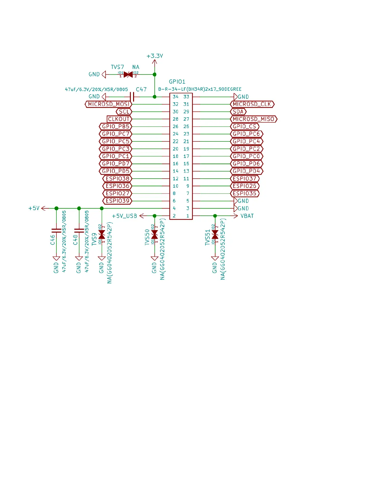
GPIO connector
Pin.1 is connected to the Li-Po battery PLUS you can connect external battery on this pin or to use battery
voltage to external circuits.
Pin. 2 is 5V power supply connected to USB-C +5V signal, you can power the board from this signal if the
USB-C is not connected. It must be regulated 5V power supply, applying more than 5V will damage the
board.
Pin.3, Pin.5, Pin.33 are GND
Pin.34 is +3.3V output capable to source up to 2A note that 200mA are used by AgonLight2
Pin.4 is +5V output capable to source up to 2A (1.8A + AgonLight2 0.2A), it’s backed by LiPo UPS so even
if there is interruption on power supply if LiPo battery is attached there will be 5V on this pin.
All GPIOs operate at +3.3V levels. This means you should not connect signals above 3.3V to these ports as
this will damage the board.
16