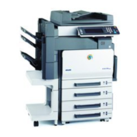
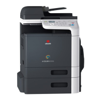
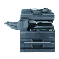
This document outlines the installation and initial setup procedures for the Color MFP 36/36 ppm (36C-9) and 30/30 ppm (30C-9) multifunction printers. It emphasizes the importance of following the steps in the correct order to prevent potential image quality issues.
Outline of Installation Procedures
The installation process involves several components, including the main machine and various optional units. The document provides a flowchart illustrating the recommended installation order for these components. Key components include:
- Main Machine: The core printing unit.
- Paper Feed Cabinets (PC-110, PC-210, PC-410): These units provide additional paper capacity.
- Large Capacity Unit (LU-302): Further expands paper capacity.
- Document Feeders (DF-704, DF-629): For automatic scanning of multiple documents.
- Finishers (FS-533, FS-534, FS-534SD): Provide stapling, sorting, and other finishing options.
- Punch Kits (PK-519, PK-520): Add hole-punching capabilities.
- Job Separator (JS-506): Separates print jobs.
- Relay Unit (RU-513): Connects various finishing options.
- Other Kits (HT-509, TK-101, MK-734, KP-101, KH-102, UK-212, MK-730, MK-735, AU-102, AU-201S, WT-506, SP-501, OC-511, CU-101, MK-745): These include heaters, transformers, various interface kits, authentication units, and covers, all contributing to the machine's functionality and security.
- Electronic System Options (EK-609, EK-608, HD-524, UK-211, SC-508, FK-514, IC-416, VI-508): These options, which can be installed in any order, enhance the machine's electronic capabilities, such as hard disk storage, security features, and fax functionality.
Caution:
Lifting the main body requires adequate manpower and proper lifting techniques to prevent personal injury, as it weighs approximately 85 kg (187-3/8 lb).
Note:
Detailed installation procedures for each option are provided in their respective manuals. The machine requires a paper feed cabinet, a dual scan document feeder, a reverse automatic document feeder, or an original cover to function. The power switch should not be turned off until all installation work is complete.
Installation Space
The document provides detailed dimensions for the machine with various options installed, ensuring proper space allocation for operation and maintenance. For example, with the DF-704, PC-210, FS-534, MK-730, and LU-302, the total width is 2124 mm (83-5/8 inches), and the depth is 818 mm (32-3/16 inches).
Pre-installation Check Items
Before installation, several environmental and power considerations must be addressed:
- Location: The machine should be installed on a level and stable surface, away from direct sunlight, hot and humid environments, dusty areas, or places with volatile and flammable substances. Good ventilation is also essential.
- Power Source: The power source must match the product specifications for voltage and frequency, and its current carrying capacity must meet or exceed the machine's requirements. The machine should be connected directly to a dedicated power outlet without using an extension cord.
- Safety: Avoid plugging or unplugging the power cord with wet or dirty hands to prevent electric shock.
Notes on Using the Touch Panel
The machine features a capacitive touch panel. Users should be instructed on its proper use:
- Interaction: Use a finger or the supplied stylus pen to interact with the touch panel. Using nails or pen tips may prevent normal response.
- Pressure: Avoid pressing the panel too hard or using sharp objects, as this can cause damage.
- Operation: The touch panel responds to quick, light finger taps.
Accessory Parts
The machine comes with several accessory parts:
- User's guide holder (1)
- Installation manual (1 set)
- Paper size label (1)
- Cap A (Black) (2)
- Cap B (White) (2)
- Cord clamp (2)
- Connector cover (1)
- Duct cover (1)
- Screw A (1)
- Screw B (3 x 8 mm) (1)
- Screw C (3 x 30 mm) (1)
- Stylus pen (1)
- Waste toner box (1)
Note: The paper size label is crucial for mounting the Large Capacity Unit LU-302.
Warning:
Packaging bags should be kept away from babies and children to prevent suffocation.
Installing the Main Body and the Paper Feed Cabinet
Caution:
The main body weighs approximately 85 kg (187-3/8 lb) and requires multiple people to transport it safely. When moving the machine, hold it by the handles on the right and left sides, keeping it level. Be careful not to pinch fingers in the transportation handles.
Note:
If the Heater HT-509, Transformer kit TK-101, or Power Supply BOX MK-734 are being installed, they should be installed concurrently with the Paper Feed Cabinet.
Removing Protective Tape, Packing, and Other Shipping Materials
The installation process involves removing various protective materials:
- Protective Tape and Materials: Remove all protective tape and packing materials from the exterior.
- Right Door: Open the right door to remove protective sheets and locking materials. Ensure the transfer roller assembly is securely in place; if not, press it into position. Save all packaging materials for future transportation.
- Tray 1 and 2: Slide out Tray 1 and Tray 2, removing protective tapes and accessory parts from inside.
- Locking Screws: Remove any locking screws.
- Caps: Attach the supplied caps A and B.
- Protective Sheets: Remove protective sheets from the top of the machine.
- Front Door: Open the front door and remove any protective tape inside.
- Developing Units: Remove protective tape from the developing units, but do not remove tape A at this stage.
- Locking Materials: Remove locking materials from four places.
- Drum Unit (K): Release the lever of the drum unit (K), slightly slide it out, and remove the protective tape. Then, slide the drum unit (K) back into the machine and lock it with the lever.
- Waste Toner Box: Install the supplied waste toner box by pushing the indicated areas.
Installing the Toner Cartridge
Note: Toner cartridges are not supplied with the machine and must be purchased separately.
- Preparation: Shake each toner cartridge 5 to 10 times (up/down and left/right) to ensure proper toner distribution. Inadequate shaking can cause issues.
- Insertion: Insert the toner cartridge into the machine, ensuring the color matches the inserting port and the blue label position aligns.
- Locking: Push the toner cartridge all the way in and rotate it clockwise to lock it.
- Repeat: Install other color toner cartridges using the same procedure.
- Close Door: Close the front door.
Installing Other Options
For other optional devices, refer to their respective installation manuals and follow the "Installation Procedures."
Mounting the Accessory Parts
- Stylus Pen: Remove the protective cover from the supplied stylus pen and discard the cover. Set the stylus pen in its designated place.
- Cord Clamp: Attach the supplied cord clamp to the scanner rear cover using one supplied screw A.
- Connector Cover: Attach the supplied connector cover to the machine using one supplied screw B.
- Duct Cover: Attach the supplied duct cover.
Connecting the Power Cord
Warning: Use the appropriate power cord to prevent fire or electrical shock.
- Connection: Connect the power cord to the machine.
- Cord Clamp: Fit the supplied cord clamp over the power cord using one supplied screw C.
- Power Outlet: Plug the power cord into the power outlet.
Starting the Machine
Open the front door, turn ON the power switch, and then close the front door.
Date & Time Setting/Time Zone Setting (Service Mode)
- Access Service Mode: Display the Service Mode screen (refer to the service manual for details).
- Date & Time Setting: Access the Date & Time Setting/Time Zone Setting screen (Stop → 1 → 1 → 4 → Clear on the control panel).
- Time Zone: Input the time zone using the up/down keys or direct keys, then touch "Entry."
- Apply and End: Touch "Apply," then "OK," and finally "END."
Note: Serial number input is only necessary for optional devices.
- Access Function: Select the Serial Number Input function (System 1 → Serial Number).
- Input: Touch the item to enter the serial number.
- End: Touch "END." Repeat for other devices.
Unit Change
This function allows users to select the message type that appears when replacement time arrives for different units.
- Access Function: Select Unit Change (System 2 → Unit Change).
- Select Message Type: Choose the appropriate message type for each unit.
- End: Touch "END."
Note: This check should be performed at the customer's site.
- Access Function: Select Non-Image Area Erase Check (Machine → Non-Image Area Erase Check).
- Open Document Feeder/Cover: Fully open the dual scan document feeder, reverse automatic document feeder, or original cover if loaded.
- Preparation: Do NOT place a document on the document glass. Clean the document glass if dirty.
- Start Check: Press the Start key.
- Result: Ensure the "Result" is "OK."
- Troubleshooting: If the result is "NG1" or "NG2," review the installation location and direction, or block light sources (e.g., fluorescent lights directly above the machine) that might interfere with the check. Perform the check again. Refer to the service manual for detailed information.
- End: Touch "OK."
Configuring Other Options
- Configuration: If any of the listed options (Dual Scan Document Feeder DF-704, Reverse Automatic Document Feeder DF-629, Stamp Unit SP-501, Fax Kit FK-514, Punch Kit PK-520/PK-519, Upgrade Kit UK-212/UK-211, Paper Feed Cabinet PC-410, Large Capacity Unit LU-302, Local Interface Kit EK-609, Security Kit SC-508, Hard Disk HD-524, Authentication Unit AU-201S/AU-102, Clean Unit CU-101, Network Fax) are installed, refer to their respective installation manuals for configuration procedures.
- Restarting: After configuring all options, exit the Service Mode and return to the initial screen. The installation manual notes that while individual option manuals may advise turning the power off and on after each configuration, this is not necessary here as all settings are made before a single restart.
Connecting the Network Cable
- Connection: Connect the main body to networking equipment (HUB) using a network cable.
- Recommended Cables:
- 10BaseT/100BaseTX: Category 5
- 1000BaseT: Category 5E, Category 6
- LED Check:
- LED1 should light up steadily for a link network connection.
- LED2 should blink according to the communications status of the ACT network.
- Cable Routing:
- No Paper Feed Options: Route the network cable through the harness guide and pass it through the notch, leaving appropriate slack to avoid interfering with cover opening/closing.
- With Paper Feed Cabinet (PC-410/PC-210/PC-110):
- Remove the rear right cover from the paper feed cabinet (two screws).
- Remove the knockout from the rear right cover using nippers.
- Route the network cable through the harness guide and three wire saddles, leaving appropriate slack.
- Route the cable through the notch and reattach the rear right cover (two screws).
Network Setting
Configure the TCP/IP address settings for the network.
- Consult Administrator: Obtain the necessary setting values from the network administrator.
- Access Settings: Menu → Utility → Administrator Settings → Enter Administrator Password → Network Settings → TCP/IP Settings → IPv4 Settings.
- Manual Input: Select "Manual Input" for IP Address Setting Method and enter:
- IP Address (controller)
- Subnet Mask (network)
- Default Gateway (default gateway)
- Confirm: Touch "OK" twice.
- Operation Check: Select Forward → Detail Settings → PING Confirmation to perform a TCP/IP operation check.
Restarting the Machine
- Power Cycle: Open the front door, turn OFF the power switch, wait 10 or more seconds, then turn ON the power switch again. Close the front door.
Adjusting Each Option
If any of the following options are installed, adjust them as necessary (refer to their respective installation manuals for "Adjustment procedures"):
- Paper Feed Cabinet PC-410/PC-210/PC-110
- Large Capacity Unit LU-302
- Dual Scan Document Feeder DF-704
- Reverse Automatic Document Feeder DF-629
- Finisher FS-534SD
- Punch Kit PK-520/PK-519
Note: After completing all steps, take a sample copy in color mode to confirm the image. If image troubles occur, power cycle the machine and redo steps E-9 "13. Date & Time Setting/Time Zone Setting (Service Mode)" to E-9 "15. Unit change."
Affixing the Paper Size Label
Affix the paper size labels corresponding to the paper sizes used in each tray. Refer to the User's Guide CD for instructions on setting paper in each tray and configuring paper types.
Installing the User's Guide Holder
Install the user's guide holder.
Affixing the Panel Sheet
Affix the supplied panel sheet to the surface of the operation panel.
Note: The panel sheet is affixed upon customer request and must be kept by the customer.
OC-511 Original Cover Installation Manual
This section details the installation of the OC-511 Original Cover.
Accessory Parts
- Original cover (1)
- Hinge cover (right) (1)
- Hinge cover (left) (1)
- Screw (2)
Warning:
Keep packaging bags away from babies and children to prevent suffocation.
Installation Procedures
- Remove Knockouts: Remove the two knockouts using nippers or a similar tool.
- Attach Hinge Covers: Attach the supplied right and left hinge covers using the two screws supplied with the original cover.
- Install Original Cover: Install the original cover onto the machine.