16
240011511 REV. C [05/31/2017]
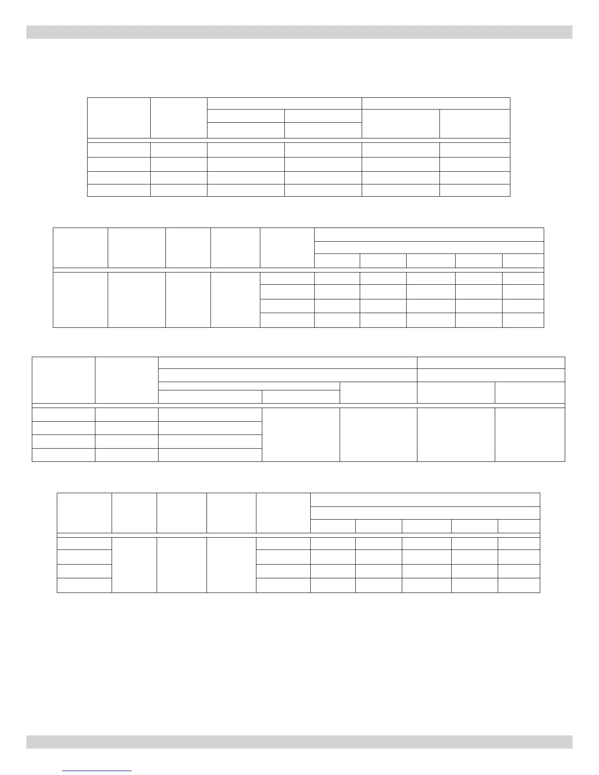
Table A-6 Direct Drive Blower Motor Setup - 1/2 HP PSC 4 Speed Motor
Furnace
Model
Blower
Heating Blower Set-Up Cooling Capacity
0.20 in. w.c. 0.50 in. w.c.
Tons
CFM Range
@ 0.5 in. w.c.
Speed Speed
LRF65 100-10T DD Low Low 3 766-1249
LRF80 100-10T DD Low Medium Low 3 766-1249
LRF90 100-10T DD Medium Low Medium High 3 766-1249
LRF100 100-10T DD Medium High High 3 766-1249
Table A-7 Direct Drive Blower Characteristics - 1/2 HP PSC 4 Speed Motor
Furnace
Model
Blower
Motor
FLA
∆T Speed
CFM
External Static Pressure – Inches w.c.
0.20 0.30 0.40 0.50 0.60
LRF
65 – 100
100-10T DD 6.0 55-85 °F
High 1455 1383 1314 1249 1160
Med-High 1427 1345 1286 1216 1128
Med-Low 1234 1170 1135 1054 973
Low 827 819 805 766 709
APPENDIX A - CHECK OUT AND ADJUSTMENTS
TIP
Formulas will assist with design of duct-work and determination of air ow delivery.
CFM = Bonnet Output / (1.085 x System Temperature Rise (∆T)
System Temperature Rise (∆T) = Bonnet Output / (1.085 x CFM)
Table A-8 Belt Drive Blower Motor Setup - 1/2 HP PSC Single Speed Motor
Furnace
Model
Blower
Heating Blower Set-Up Cooling Capacity
0.20 in. w.c. 0.2 in. w.c.
Pulley
Belt Tons CFM Range
Motor Blower
LRF65 100-10T 3-1/4" X 1/2" 3 T.O.
6" X 3/4" 4L370 2.5-3.0 960-1300
LRF80 100-10T 3-1/4" X 1/2" 2 T.O.
LRF90 100-10T 3-1/4" X 1/2" 1 T.O.
LRF100 100-10T 3-1/4" X 1/2" 0 T.O.
Table A-9 Belt Direct Drive Blower Characteristics - 1/2 HP PSC Single Speed Motor
Furnace
Model
Motor
FLA
∆T Blower
Motor
Pulley
Turns Out
CFM
External Static Pressure – Inches w.c.
0.1 0.2 0.3 0.4 0.5
LRF65
7.9 55-85 °F 100-10T
0 1400 1300 1183 1052 904
LRF80 1 1307 1190 1061 915 752
LRF90 2 1217 1076 927 744 544
LRF100 3 1110 960 793 536 248
A.5 Blower Setup