Do you have a question about the Olsen G95V80 and is the answer not in the manual?
Defines DANGER, CAUTION, WARNING, and NOTICE symbols.
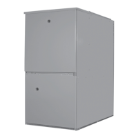
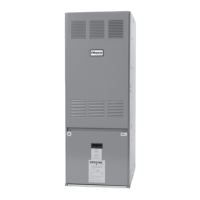
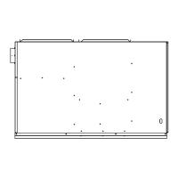
Provides diagrams and tables for physical dimensions and clearance requirements.
Details requirements for CO detectors, signage, and inspections in MA.
Outlines manufacturer requirements for venting systems and general instructions.
Explains load calculation, ductwork impact, and required temperature rise.
Covers selecting a suitable location and access for servicing.
Addresses chemical contaminants and horizontal mounting methods.
Specifies clearances to combustibles, service access, and floor installation rules.
Covers airflow importance, duct sizing, installation steps, and definitions.
Discusses replacing Category I furnaces, common venting, and testing procedures.
Lists approved materials for combustion air and vent piping in US and Canada.
Details combustion air needs based on location and airborne contaminants.
Addresses safety warnings and air provisions for indoor combustion air.
Details air calculation methods for different space types and configurations.
Covers venting slope, length, support, insulation, and horizontal termination rules.
Provides tables for vent lengths and diagrams for venting configurations.
Details termination clearances for Canada and the US, and location advice.
Explains non-direct and direct vent installations, and combustion air piping.
Covers termination details for combustion air, concentric kits, and location advice.
Highlights cautions for improper termination and rules for multiple furnace venting.
Specifies termination clearances and routing options for different installations.
Provides guidance on pressure switch mounting and venting installation steps.
Illustrates direct and non-direct vent termination clearance zones.
Presents detailed clearance requirements for direct vent terminations.
Presents detailed clearance requirements for non-direct vent terminations.
Details top and left side venting installation procedures and diagrams.
Covers right side venting installation procedures and diagrams.
Provides installation steps and diagrams for horizontal left top venting.
Details installation for horizontal right side venting with diagrams.
Covers installation for horizontal right top venting with diagrams.
Provides installation steps and diagrams for downflow left side venting.
Details installation for downflow right side venting with diagrams.
Guides on installing the condensate trap, hose, and piping, including cautions.
Explains condensate neutralizers, bypass configurations, and related notices.
Covers warnings for gas supply, conversion requirements, and utility gas usage.
Details gas piping installation, shut-off valves, inlet pressure, and leak testing procedures.
Addresses purging gas lines safely and outlines conversion types.
Explains conversion procedures for high altitude and fuel types (natural to LP, LP to natural).
Provides detailed steps for conversions and checking inlet gas pressure.
Guides on setting manifold gas pressure and includes regulator adjustment warnings.
Covers wiring connections, power shutoff, and grounding requirements.
Details 120V furnace connection, junction box, and ignition control components.
Provides instructions for thermostat compatibility, staging, location, and wiring.
Explains power provisions for optional accessories.
Covers the process for starting, stopping, and initial checks during startup.
Details the furnace's operational sequence and how to check its input.
Guides on measuring and verifying the temperature rise for correct airflow.
Explains how to calculate airflow and adjust blower speeds using jumpers.
Covers blower speed adjustment, dehumidification, and blower timing features.
Describes the operation of the continuous fan mode.
Emphasizes safety during maintenance and provides guidance on air filter inspection and cleaning.
Covers motor lubrication, vent terminal inspection, operating tips, and annual service.
Details inspection and cleaning of heat exchanger, burners, drainage, and blowers.
Visual guide to diagnosing and resolving furnace operational issues.
Explains fault conditions indicated by red LED flashes.
Covers remaining red LED codes and how to access fault history.
Provides a detailed wiring diagram for the furnace's electrical system.
A checklist to ensure proper venting installation according to guidelines.
Lists part numbers and descriptions for common replacement components.