17 GAS SUPPLY AND PIPING
Gas Piping
In Canada, the gas piping should be installed in accordance with
CAN/CGA-B149.1 and 2, and in accordance with any local codes.
In the United States, the gas piping should be installed in accordance
with NFPA 54 / ANSI Z223.1 and any local codes.
If local codes allow the use of a exible gas appliance connector,
always use a new listed connector. Do not use a connector, which has
previously serviced another gas appliance.
NOTICE
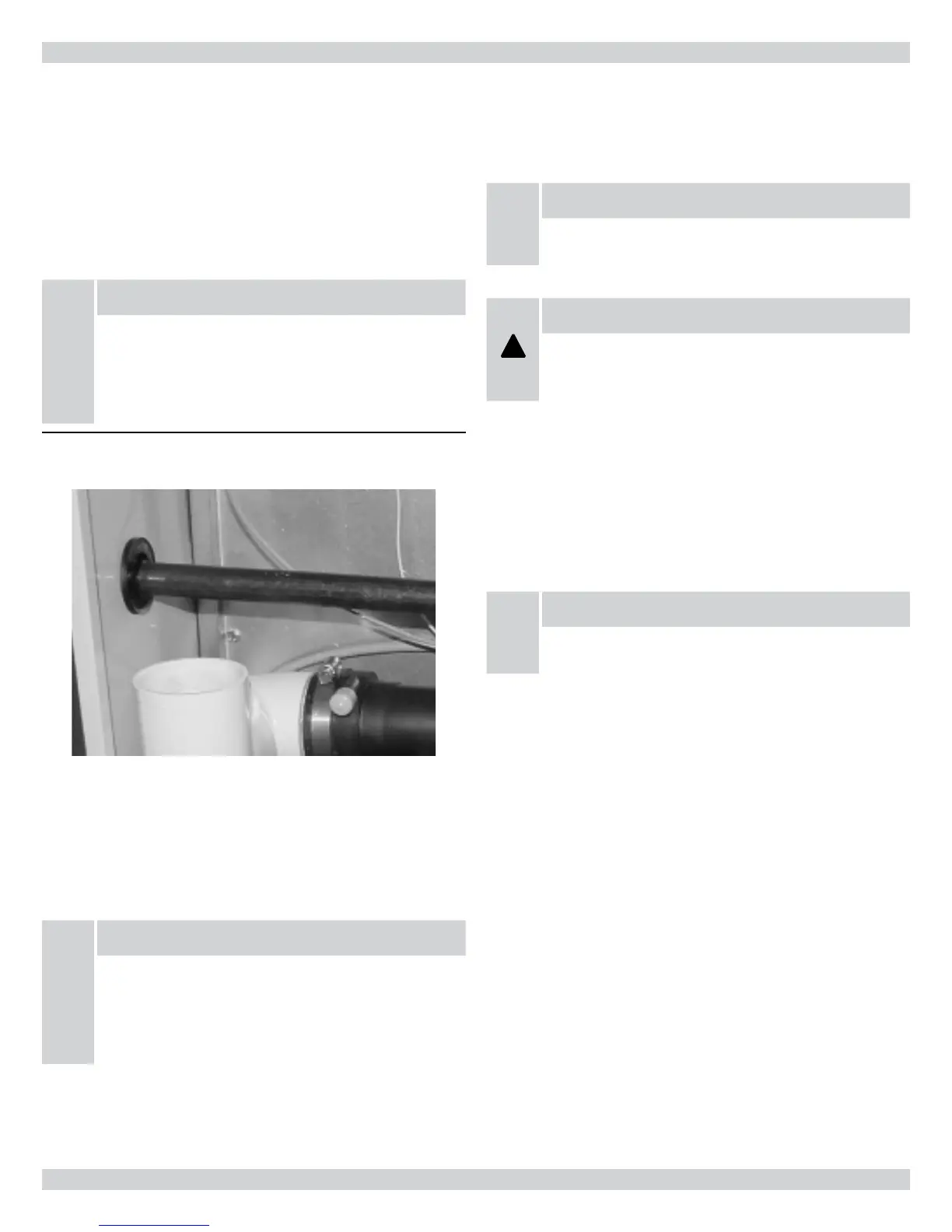
IMPORTANT: To maintain a good seal in the burner area,
the gas piping through the side panel into the furnace
must be ½” A53 black iron pipe. e pipe passes through
a special rubber grommet that is custom manufactured to
seal tightly around the gas pipe.
Figure 28 - Furnace Gas Pipe Connections (Note Rubber
Grommet)
e gas piping may enter the furnace from either side. Once the
routing of the gas pipe is determined, select and remove the appli-
cable knockout and install the grommet within the hole.
Install a BMI ground joint union between the gas valve and the side
panel to allow easy removal of the burner for service purposes.
NOTICE
IMPORTANT: Always use a backup wrench to prevent
twisting of the control assembly and gas valve. Any strains
on the gas valve can a ect positioning of the ori ces
relative to the burners. is could result in faulty burner
operation.
Install a manual gas shut-o valve and dirt pocket as close to the
furnace as possible. Some local codes call for the manual gas shut-o
valve to be located between 4 to 5 feet above oor level to prevent
tampering by small children. Ensure that the valve is readily acces-
sible.
NOTICE
IMPORTANT: Ensure that the manual shut-o valve and
gas valve are not subjected to high pressures.
!
WARNING
Indicates an imminently hazardous situation which, if not
avoided, may result in death, serious injury or substantial
property damage.
Gas Inlet Pressure
e natural gas inlet supply pressure should be 5” to 7” w.c. (7” w.c.
recommended). e LP gas inlet supply pressure should be 11” to
14” w.c. (12” w.c. recommended). ese pressures must be main-
tained while all other gas red appliances are operating at maximum
conditions.
NOTICE
IMPORTANT: Do not exceed 14” w.c. inlet pressure with
either fuel.
e gas valve has two adjustable internal
regulators for controlling burner manifold pressure. Burner mani-
fold high re and low re pressures are listed on the furnace rating
plate.
Leak Testing
All new gas piping installations should be pressure tested as speci ed
by CAN/CGA-B149.1 & 2, or NFPA 54 ANSI Z223.1 or ANSI/NFPA
58, “Standard for the Storage and Handling of Lique ed Petroleum
Gases.”
Gas piping that has not been pressure tested, from the manual
shut-o valve to the furnace gas valve for example, should be leak
tested using an electronic combustible gas detector, a commercially
prepared leak detector, or other locally approved method. A leak
detector solution can be prepared by mixing a small quantity of dish
detergent with water and daubing it onto the gas piping, especially
the joints.
35