!
WARNING
DISCONNECT THE ELECTRICAL POWER SUPPLY TO
THE FURNACE BEFORE ATTEMPTING ANY MAIN-
TENANCE. FAILURE TO DO SO CAN CAUSE ELEC-
TRICAL SHOCK RESULTING IN PERSONAL INJURY
OR LOSS OF LIFE.
!
CAUTION
Label all wires prior to disconnection when servicing
controls. Wiring errors can cause improper and dangerous
operation.
Always verify proper operation a er servicing.
Air Filter
e lter should be inspected frequently and cleaned as necessary.
We recommend a monthly inspection at rst, perhaps coinciding
with the arrival of the monthly fuel bill as a reminder. e frequency
may be increased or decreased depending on experience and condi-
tions.
Avoid the use of the berglass throw-away lters. ey tend to block
up quickly, which may result in higher than normal operating tem-
peratures, and lower e ciency.
Some paper media high e ciency lters, sometimes identi ed as
HEPA lters can do an e ective and excellent ltration of the air;
however, some models may also cause a large pressure drop across
the lter. e contractor should assess the capabilities of the duct
system to deliver su cient air ow if this type of lter is considered.
Recommended:
Electronic air lters using electrostatic precipita-
tion to remove dust are an excellent ltration device. A 16” x 25”
model is an ideal t with this furnace in the case of a side mounted
return air inlet. e furnace control module is supplied with electri-
cal terminals for use with electronic air cleaners.
A 16” x 25” x 1” lter kit part number 550001458 can be ordered for
use on this appliance. is kit includes the lter rack and washable
lter.
NOTICE
NOTE: If two return air inlets are used, both must be
equipped with lters.
!
CAUTION
Do not operate the furnace for prolonged
periods of time without an air fi lter.
A portion of the dust entrained in the air
may lodge in the supply air ductwork and
registers. Any recirculated dust particles
will be heated and charred by contact with
the furnace heat exchanger. This residue
will soil ceilings, walls, drapery, carpets,
and other household articles.
If a call for cool (Y) occurs simultaneously with the call for fan (G),
the call for cool overrides the call for fan and the blower remains o
for the cooling on delay period.
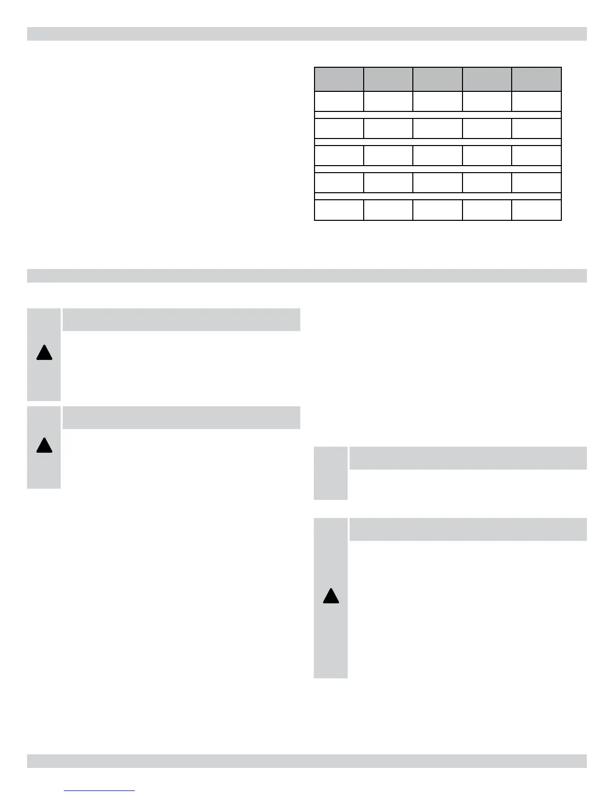
23 AIR FLOW
TABLE 12 - CONTINUOUS FAN CFM
MODEL
Motor
HP
COOL
Jumper
ADJUST
Jumper
Continuous
Fan (CFM)
95V060-3 1/2 A NORM 600
95V080-3 1/2 A NORM 600
95V080-4 3/4 A NORM 825
95V100-5 1 A NORM 865
95V120-5 1 A NORM 930
Note: Moving the ADJUST jumper from the NORM position to the (+)
or (-) position will increase or lower the continuous fan CFM by 15%
24 MAINTENANCE AND TROUBLESHOOTING
47
 Loading...