5.
Measure furnace gas inlet pressure with burners ring. Inlet
pressure must be within the range speci ed on the furnace
rating plate. 5-7” w.c (Natural Gas) or 11-14” w.c. (LP). If the
inlet pressure di ers from the rating plate, make the necessary
adjustments to pressure regulator, gas piping size, etc. and/or
consult with local gas utility.
6.
Turn o gas and electrical supply to furnace, remove the ma-
nometer hose from the inlet pressure tap boss, and tighten the
inlet pressure tap screw using the 3/32” Allen wrench. (clock-
wise, 7 in-lb minimum).
7.
If working on a natural gas system, contact the gas utility. ey
may insist on any service regulator adjustments being made by
their own sta .
If problems were encountered with obtaining enough pressure on
the manifold, rst examine the gas piping system to ensure that it
is correctly sized. Pipe sizing is speci ed in CAN/CGA-B-149.1 &
2, and in NFPA 54 / ANSI Z223.1. Be sure to check for restrictions,
partially closed valves, etc.
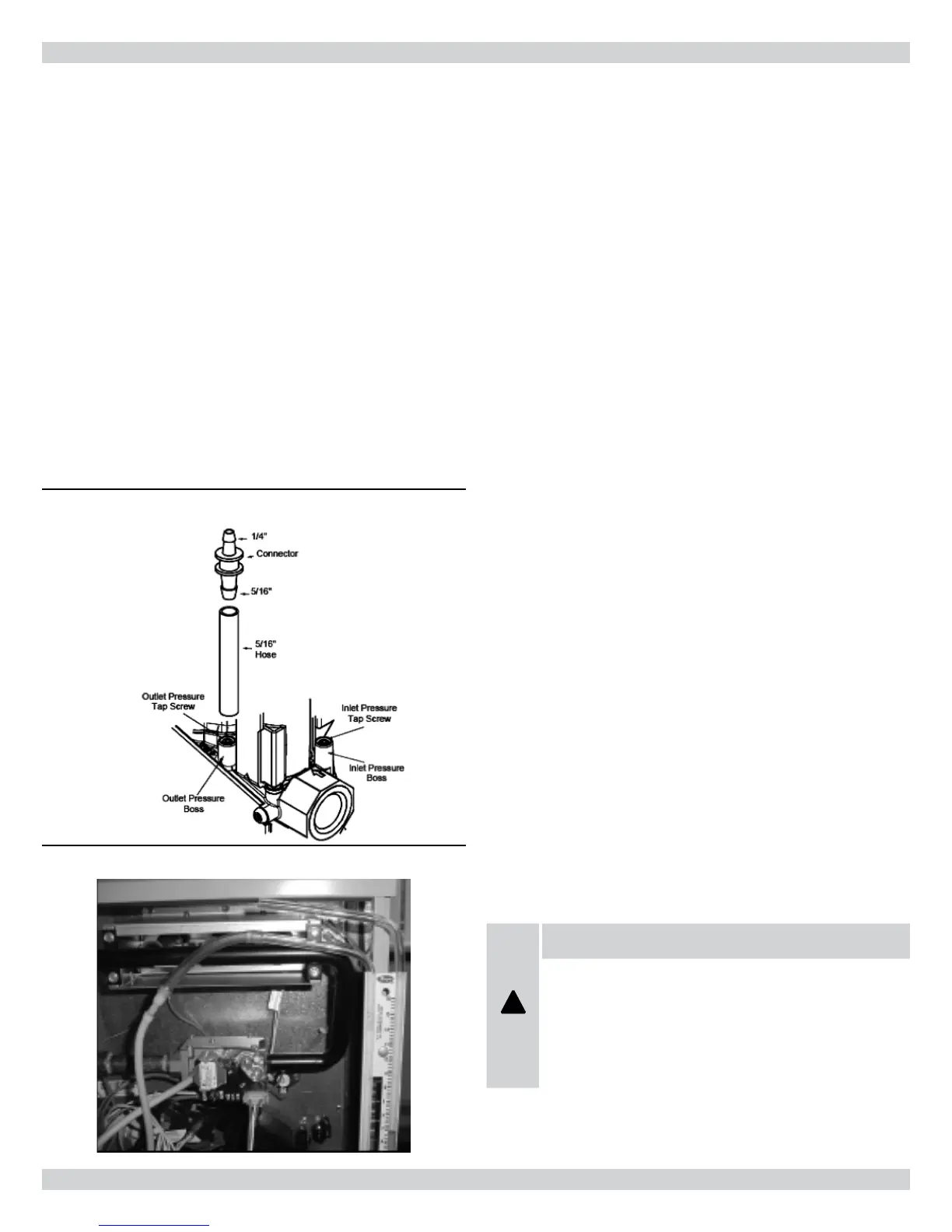
Figure 32 - Valve Pressure Kit
Figure 33 - Manometer Measuring Gas Inlet Pressure
18 CONVERSIONS
Setting The Manifold Gas Pressure
When the installation is completed to the “Start-up & Setup”
stage, test the gas manifold pressure by following these steps:
White-Rodgers 36G54 Two Stage Gas Valve.
1.
Turn o the gas and electrical supply before proceeding.
2.
Back outlet pressure test screw (outlet pressure boss, see g.31)
out one turn (counterclockwise, not more than one turn) with
a 3/32” Allen wrench. Attach a hose and calibrated U-tube
manometer to the outlet pressure boss. Hose should overlap
boss 3/8”. e manometer must have a scale range of at least 0”
to 15” of water column.
3.
Turn on the gas supply and electrical power
to the furnace and energize main solenoid by connecting R to
W1 on the integrated control board. Do not energize the HI
solenoid
4.
Remove regulator cover screw from the low outlet pressure
regulator adjust tower ( g.31) and turn the plastic regulator
adjustment screw clockwise to increase manifold pressure or
counterclockwise to reduce manifold pressure. Always adjust
regulator according to original equipment manufacturer’s
speci cations listed on the appliance rating plate. Replace regu-
lator cover screw.
5.
Energize main solenoid as well as the HI terminal by connecting
R to W1 and W1/W2 on the integrated control board. Remove
regulator cover screw from the high outlet pressure regulator
adjust tower ( g.31) and turn the plastic regulator adjustment
screw clockwise to increase manifold pressure or counterclock-
wise to reduce manifold pressure. Manifold pressure should be
set to 1.5” w.c low re, 3.5” w.c high re for natural gas, 4.0” w.c
low re, 10.5” w.c high re for LP gas. Always adjust regulator
according to original equipment manufacturer’s speci cations
listed on the appliance rating plate. When the correct pressure
has been established, securely replace the regulator cover screw.
6.
Turn o the gas and electrical supply to the furnace.
!
WARNING
ALL REGULATOR ADJUSTMENTS MUST BE DONE
BY A TRAINED, QUALIFIED TECHNICIAN. IMPROP-
ER MODIFICATIONS OR ADJUSTMENTS CAN RE-
SULT IN FIRE OR EXPLOSION CAUSING PROPERTY
DAMAGE, SEVERE PERSONAL INJURY OR LOSS OF
LIFE.
38
 Loading...