12 VENTING GUIDELINES
TABLE 6 - DIRECT AND NON-DIRECT VENT LENGTHS
MAXIMUM ALLOWABLE LENGTH OF EXHAUST OR INTAKE
MODEL
PIPE
SIZE
NUMBER OF 90° ELBOWS
NOTES
0123456
60
1½” 25 20 15 10 5 - -
1. Count concentric vent fi tting as
straight pipe.
2. Use medium or long sweep
elbows where possible.
3. One 90° elbow is equivalent to
two 45° elbows.
4. For direct vent, the listed lengths
are allowed for each vent (intake
and exhaust).
5. For non-direct vent, the listed
lengths are allowed for exhaust.
The intake should have a 1½”
or 2” snorkel intake fi tting.
(
Figure 9
)
6. Include the 2 vestibule elbows
when calculating total vent length
for all models.
2” 75 70 65 60 55 50 45
3” 100 95 90 85 80 75 70
80
2” 50 45 40 35 30 25 20
3” 100 95 90 85 80 75 70
100
2” 50 45 40 35 30 25 20
3” 100 95 90 85 80 75 70
120 3” 100 95 90 85 80 75 70
When 1½” or 3” pipe is used, exit the cabinet with 2” pipe. Reduce or increase immediately after exiting the
cabinet making provisions to secure the vent bracket between cabinet and fi tting.
Use of a concentric termination reduces the allowable length by 5 feet from lengths shown in this table.
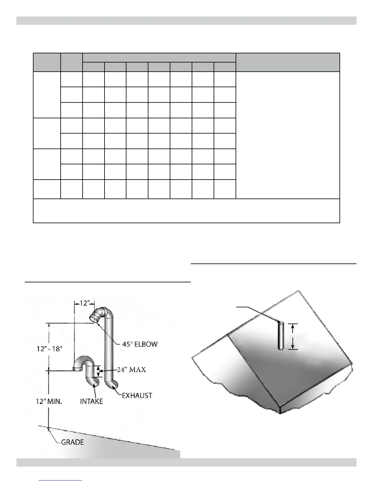
Figure 11 - Vertical Venting
Roof Termination
Exhaust
18” MIN.
Figure 10 - Periscoped Vent Detail
19
 Loading...