22
240011511 REV. C [05/31/2017]
APPENDIX C - SEQUENCE OF OPERATION AND TROUBLESHOOTING
HLRF Humidity control is connected. Humidier connections are energized when the oil burner motor is energized.
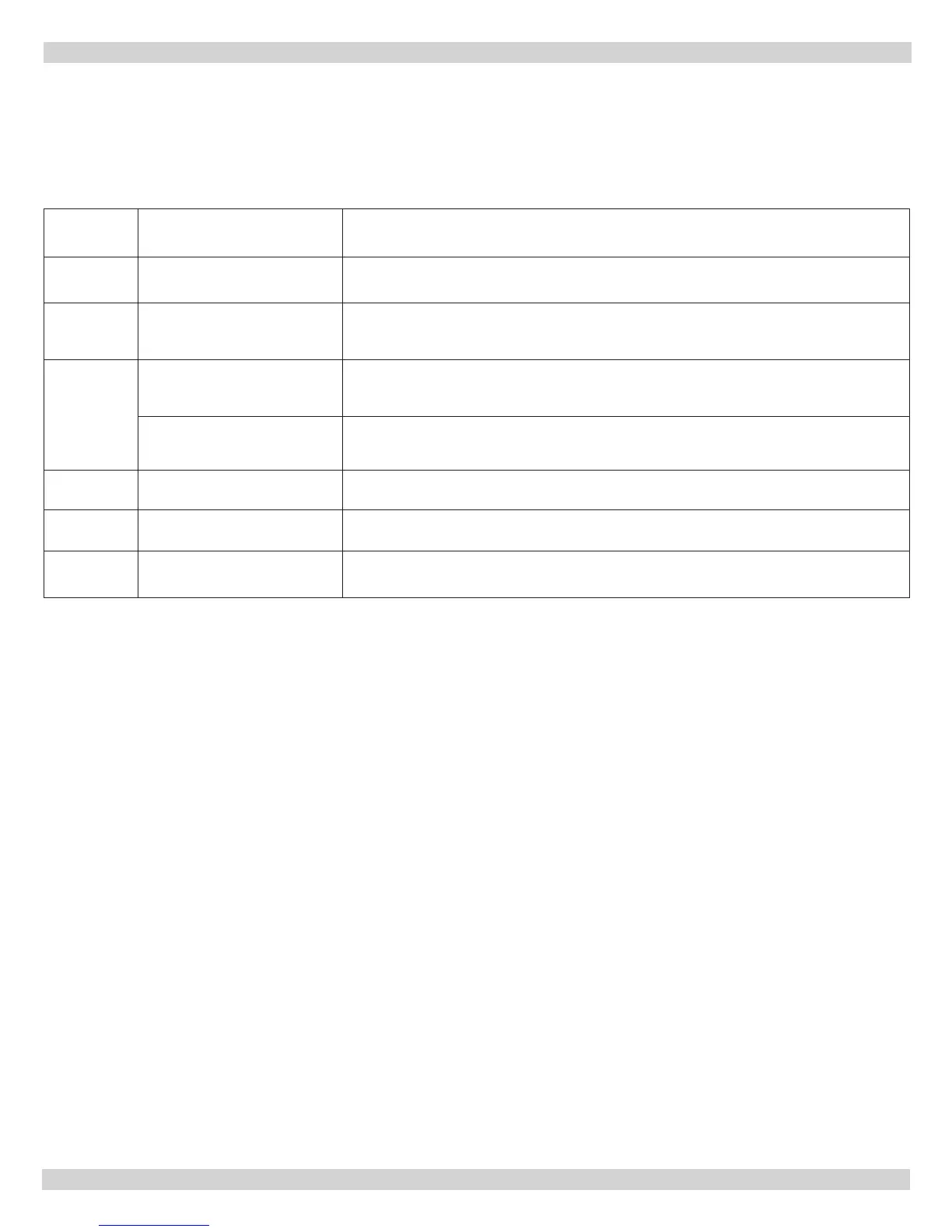
Mode Action System Response
HEAT Thermostat call for heat "W"
The 24 VAC input signal is passed to pin 2 of P1 and will drive the K1 relay that provides
dedicated contacts to the T-T input of the oil primary control. Blower runs on heating speed
prole.
COOL
Thermostat calls for single
stage cooling or second stage
of two stage cooling "Y/Y2"
The 24 VAC input signal is passed to pin 14 of P1. Blower runs on cooling speed prole.
Thermostat calls for rst stage
of two stage cooling "Y1" while
"Y/Y2" is not calling
The 24 VAC input signal is passed to pin 6 of P1. Blower runs at 80% of cooling speed
prole.
FAN Thermostat calls for fan "G"
The 24 VAC input signal is passed to pin 15 of P1. Blower runs at continuous low speed
prole which is 50% of cooling speed.
DEHUMID
Thermostat calls for
Dehumidication "DH"
The 24 VAC input signal is passed to pin 10 of P1. Blower runs according to "Y1" and
"Y/Y2" calls as noted above.
REVERSING
VALVE
Thermostat calls for reversing
valve "O"
The 24 VAC input signal is passed to pin 9 of P1. Blower runs according to "Y1" and
"Y/Y2" calls as noted above.
Table C-2: 1168-1 ECM Tap Board Sequence of Operation (LRFV)
Thermostat Input LEDs (LED 1-5, LED 8)
Six green LEDs are placed behind their respective thermostat connections (Y1, Y/Y2, G, DH, O, W) and
illuminate whenever a call is present.