System Connection
i--SPEED 19
Chapter 4 System Connection
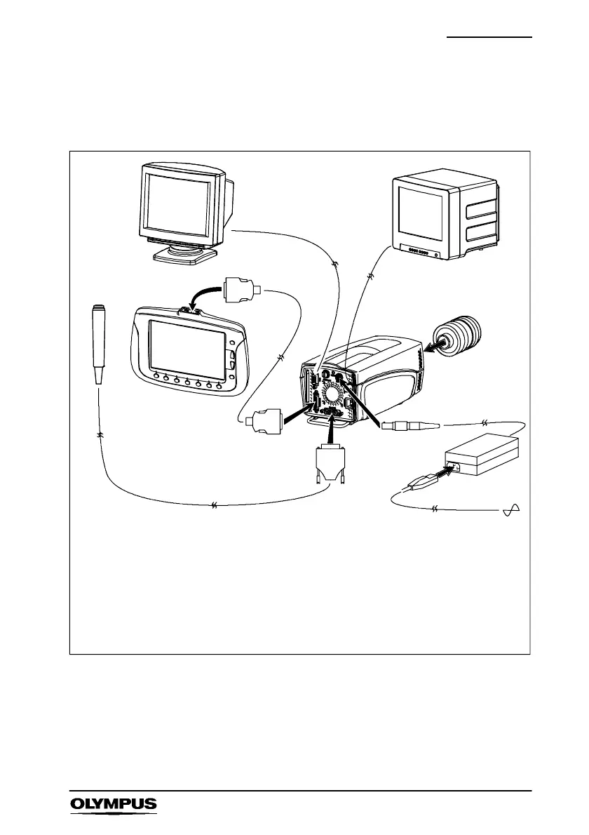
Refer to the diagram shown below and connect the system.
Key
1 Trigger switch 6 Mains power cable
2 CDU (Controller Display Unit) 7 C--Mount lens*
3 Controller cable 8 VGA cable *
4 Camera 9 Composite video BNC cable*
5 Power supply unit (PSU)
1
2
3
4
5
6
7*
8*
3
*not supplied in the standard set
9*
1
Optional
PC/TV monitor