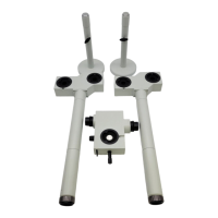
15
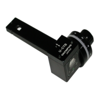
U-CWE2
} The U-CWE2 indicates retardation values (1 to 4 λ) using
two scales on the side. Read the reading of the scale for
the module used (U-TAD or U-PA).
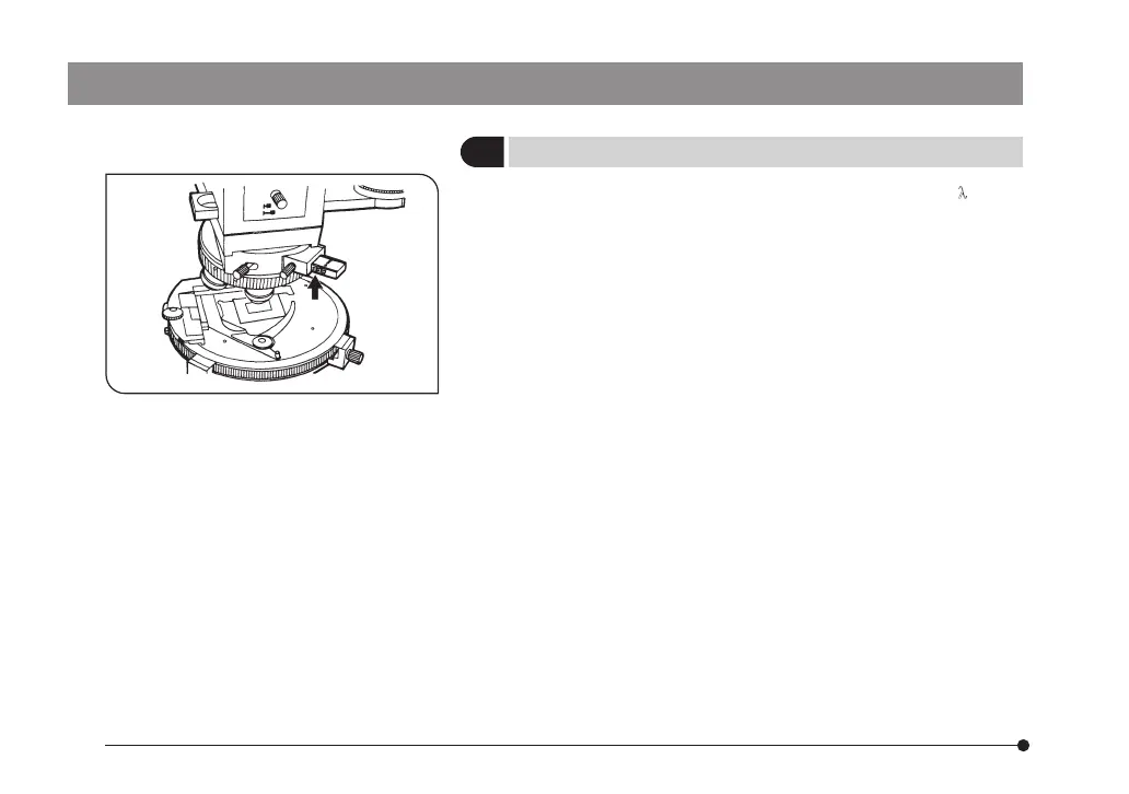
1. Slide the U-CWE2 and adjust so that the measuring point
on the specimen becomes dark.
2. At this point, note the value indication on the side of the
U-CWE2 seen at the edge of the adapter. This reading shows
the approximate range of the retardation at the measuring
point. (Arrow indicated position Fig. 4)
3. Based on this estimate and using the interference color chart
(*), find the retardation by comparing the background color
outside the measuring point and the color at the measuring
point when the U-CWE2 is removed from the optical path.
(*) Download the file of interference color chart from OLYMPUS
webside (below mentioned URL).
http://www.olympus-ims.com/microscope/bx-pol-chart
The downloaded file includes multiple interference color
charts which differ depending on the type of light source
unit. Select the interference color chart applicable to your
light source unit.
3
Measuring Retardation
Fig. 4