FM Transmitter
Sistemas Electrónicos S.A EM 100 DIG
Technical Manual - v1.2 - November 2005 11
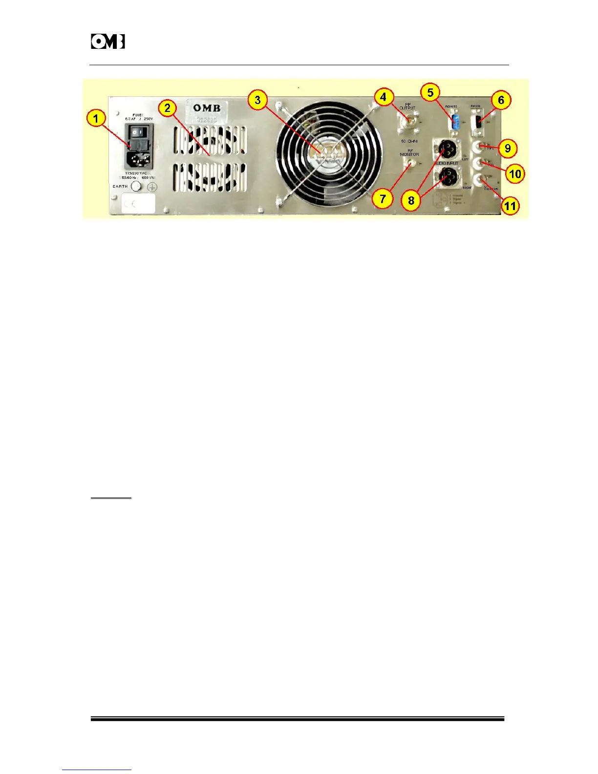
Figure 1- 3: EM-100 DIG Back panel.
1 - Mains IEC ON/OFF switch,mains voltage selector,socket & fuses block (depending on Power
Supply used).
Please note that, in case of using Power Transformers' Supplies having taps, the transmitter is normally
factory pre-set for 220-240V
AC
nominal Mains voltage as a security factor.
2 - Main Power Supply's hot air exhaust from internal cooling blower (depending on Power Supply
used).
3 - RF Power Module's hot air exhaust from cooling fan.
4 -Output RF connector. Type "N" female.
5 - Remote operation DB-9 male connector, whose connections are the following:
6 - RS-232 serial interface connector. This RS-232 port manages only Tx,Rx and Return data
signals, with no handshake.Being the two former wired signals inverted to the port,it needs a simple
straight wired serial cable with appropriate connectors: usually a female DB-9 or DB-25 to the
PC port and a male DB-9 connector at the transmitter end. Appropriate OMB software is required
for communication.
WARNING
: Do not connect the serial cable with neither transmitter nor PC turned on.
7 - RF sample output for frequency measuring or RF signal monitoring, BNC female type
connector ( -50dBc).
8 - Right & left channels audio input XLR balanced female connector.For using internal stereo
coder. (See equipment's rear panel for pin connections).
9 - MPX input connector.Type BNC female.For use in pre-coded stereo multiplex signal input. Flat
response from 10Hz to 100KHz to feed stereo multiplex signal. Hi - Z unbalanced input (10K:).
10 - AUX connector. Unbalanced Hi-Z BNC female connector,to feed a RDS or SCA coder output
signal.
11 - LF MONITOR output connector. Baseband modulation output for monitoring, re-broadcasting or
RDS external synchronization. BNC female type, unbalanced Hi-Z (10K:).
 Loading...