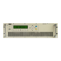
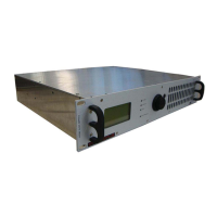
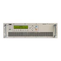
FM Transmitter
Sistemas Electrónicos S.A EM 100 DIG
Technical Manual - v1.2 - November 2005 14
2.1 Introduction.
Before proceeding further, make sure that mains voltage corresponds to the factory-set value (usually
220/240V
AC
). In case it differs, change to the proper value. Install the transmitter in a dry, ventilated
and possibly dust-free environment, so that it will operate in the +10 ~+35°C temperature range.
Connect the Transmitter to the load and audio source using suitable cables and connectors, which
should be periodically inspected.
The EM-100 DIG has many features of a hi-fi Transmitter and should be installed and audio-wired with
the same care, avoiding earth loops as much as possible. When these conditions are met,the
transmitter performs superbly.
This Transmitter is adequately shielded and can be installed close to the program Studios without fear
that it will affect the audio equipment.This arrangement has the advantage that the audio
level,deviation and power parameters can be continually monitored. EM-100 DIG can also be
installed away from the studio and connected with several meters of LF coaxial cables with no
adverse effect on modulation quality. A remote installation usually requires a STL (Studio to
Transmitter Link).
As the final modulation performance is dependent on the whole system arrangement, carefully
consider the whole system planning.
2.2 System connection.
1 - Connect the N-type output connector, marked “RF OUT ” to the antenna or RF Power Amplifier with
low-loss 50:coaxial cable, tested to 500W of peak-power rating in the frequency range used.
Andrew LDF4 or 1/2" Cellflex line can be used in some short hops.
2 - Connect the audio inputs as required for operation and detailed in the following chapters for
various situations. If needed, connect the serial and / or parallel remote control I/O ports as
required, or jump this step to a subse-quent moment.
3 - Switch-off the mains rear switch and connect the transmitter to mains and ground system.
4 - Before turning on Transmitter in the system, pre-set if possible frequency and power separately on
a dummy load, to avoid system problems at the first turn-on of the equipment. If this cannot be
done, check that the transmitter's maximum output power (100W)) does not harm any external
supplementary amplifier stage (if any).
5 - Turn-on the rear panel mains switch, then push-on the front panel on/stand-by switch to operate
the transmitter and check that:
-All LEDs and the display briefly lights on and off for the initial check.
-The yellow <STAND-BY> LED turns off.
-The green “<LOCK> LED must light up after a very short time,when frequency is locked at PLL.
Once locked, the RF power will rapidly increase to the pre-set level in a mild increasing mode. Once
preset power is reached, the <ON THE AIR> LED will light completely, if the power is set >5W (at least
5.1W). Till that moment it will turn off and on, signalling the RF power is present but not correct.
Equipment is now functioning in the pre-set mode, delivers power and can be accessed to be
programmed or simply to monitor its functions with the front panel display.