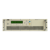
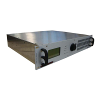
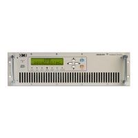
FM Transmitter
Sistemas Electrónicos S.A EM 100 DIG
Technical Manual - v1.2 - November 2005 18
Therefore, the audio level shall be constantly and correctly monitored and adjusted, to prevents as
much as possible, the internal limiter from cutting in. On the other hand, the audio level should be as
high as possible, to achieve the best signal/noise ratio on reception.
The tendency to over-process audio signals is common in many local broadcasting stations:some
sort of processing is advisable and we recommend using a top grade multiband compressor, but
not to compress the signal too much as this impairs the original dynamics.
The audio response of the EM-100 DIG transmitter is extremely flat, without perceivable loss on low
and high audio frequency: for this reason large frequency alterations of the audio signal supplied by
using a so-called “frequency equalizer,” are not advisable. An increase of the low and high
frequency contents of the audio signal by more than a few dB can cause general degradation of
modulation dynamics and improper functioning of the limiter.
2.3.4 RS232 Serial Port.
The RS-232 port manages only Tx, Rx and Return data signals, with no handshake. Being the two
former signals wired inverted to the port, it need a simple straight wired serial cable with appropriate
connectors:usually a female DB-9 or DB-25 female to the PC port and a male DB-9 connector at the
transmitter end. Appropriate software is needed for communication. OMB can provide this software
and also Telemetry Equipment at request. Do not connect the cable with neither transmitter or PC
energized.
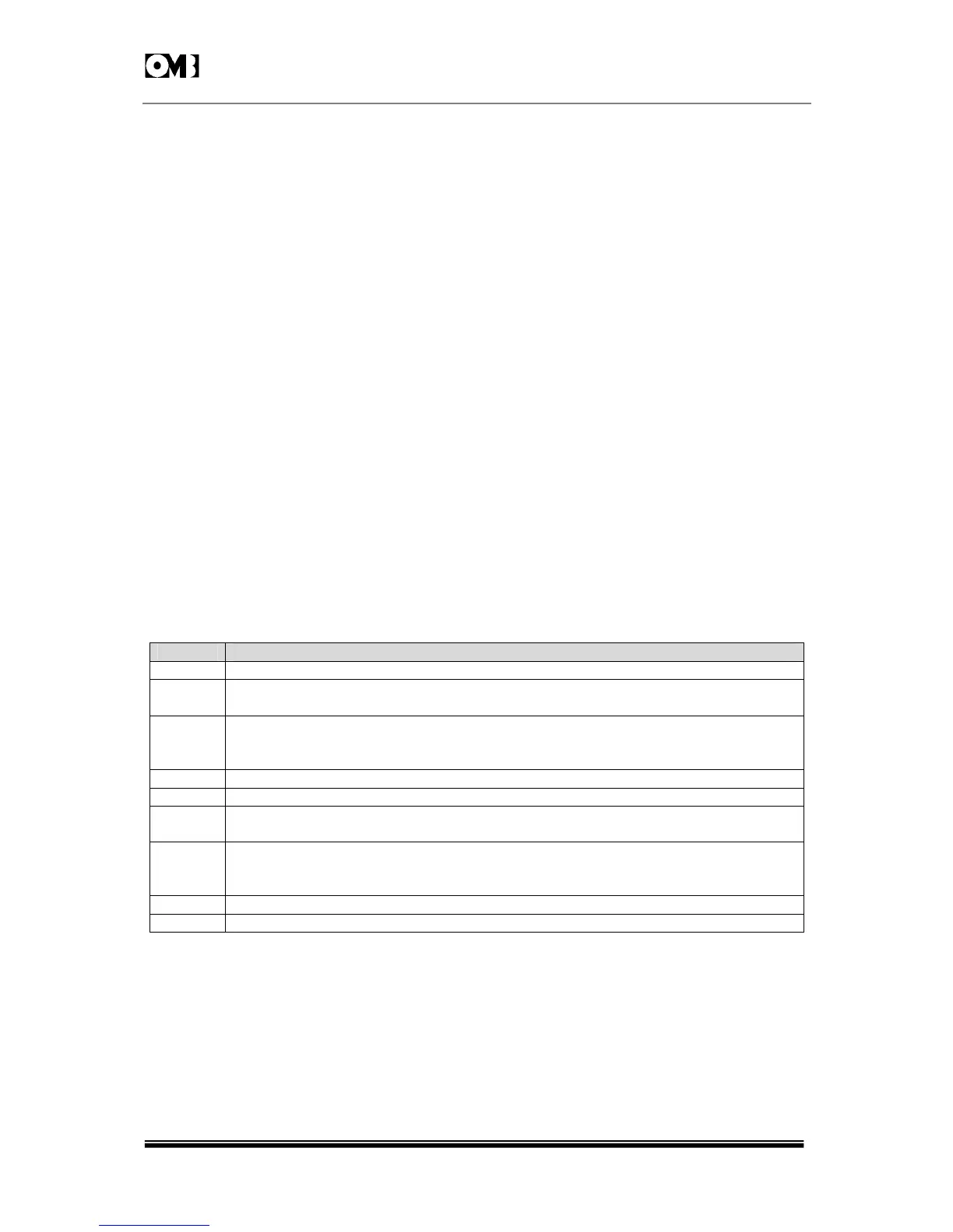
2.3.5 Parallel REMOTE Port.
Remember that this port accommodates some lines for simple direct control / monitor on a DB-9
male connector. They are:
PIN DESCRIPTION
1
GND
2
ON THE AIR
A +12V/10k: signals that the transmitter is delivering substantial RF power
3
FORWARD POWER
A signal proportional to transmitted power is present, with a pseudo square law.
Range is 0-5V
DC
/10K: impedance.On EM-100 DIG, 5V stands for 100W.
4 -
5
GND
6
RF ENABLE
A shorted circuit to ground disables RF. Signal level +10V
DC
/1mA max.
7
FAIL URE
Logic low signal means alarm. Correct functioning is signalled by +12V/10K:
Maximum current sinking capability <10mA.
8
GND
9 -