EasyManua.ls Logo

Omcan SP300AT User Manual

Default Icon
24 pages
To Next Page IconTo Next Page
Page #1 background imageLoading...
Page #1 background image
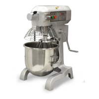
General Purpose Mixers
Instruction Manual
Version 1.2
1-800-465-0234
www.omcan.com
3115 Pepper Mill Court, Mississauga, ON, L5L 4X5
4450 Witmer Industrial Estates, Unit 4, Niagara Falls, NY, 14305

Questions and Answers:

Omcan SP300AT Specifications

General IconGeneral
ModelSP300AT
TypeSpiral Mixer
CategoryMixer
Capacity30 Liters
ConstructionStainless Steel
Bowl Capacity30 Liters
Speed Settings2

Summary

General Information

Check Package Upon Arrival

Inspect mixer for shipping damage upon receipt, document issues within 24 hours.

Mixer Suitability and Features

Overview of mixer suitability for production environments and key features.

Technical Specifications

Model Specifications Table

Detailed specifications for VFM10, SP200A, SP300A models.

Installation

Uncrating, Location, and Electrical Connections

Steps for unpacking, positioning, and connecting the mixer electrically.

Initial Operation Check

Steps to perform before first use, including bowl installation and power-up.

Operation Instructions

Safety Precautions and General Operation

Safety warnings, power supply, speed change, and shutdown procedures.

Operational Notes and Maintenance Tips

Grounding, cleaning, and placement guidelines for optimal operation.

VFM10B Controls

Explanation of the On/Off switch and features for the VFM10B model.

Model-Specific Controls

SP200AT and SP200A Controls

Details on On/Off switches and timers for SP200AT and SP200A models.

SP300AT Controls

Instructions for SP300AT controls including switches and speed lever.

SP300A Controls and Bowl Installation

SP300A Controls

Details on the On/Off switch and speed lever for the SP300A model.

Installing Mixer Bowls

Step-by-step guide for correctly installing mixer bowls on all models.

Mixer Attachment Installation

VFM10B Attachment Installation

Instructions for attaching accessories to the VFM10B mixer.

SP200AT/SP200A Attachment Installation

Guide for attaching accessories to SP200AT and SP200A mixers.

SP300AT/SP300A Attachment Installation

SP300AT/SP300A Attachment Guide

Step-by-step instructions for installing attachments on SP300AT/SP300A.

Maintenance and Troubleshooting

Routine Cleaning and Greasing

Daily cleaning of bowl/attachments and periodic greasing of gearbox.

Troubleshooting Common Issues

Common problems, their causes, and solutions for mixer operation.

Professional Servicing Warning

Warning to seek professional service for equipment malfunctions.

Mixer Capacity Chart

Product Capacity Guidelines

Table detailing product capacities for different mixer models and agitators.

Capacity Adjustment Factors

Notes on factors affecting capacity, like flour type and temperature.

Parts Breakdown for VFM10B

VFM10B Exploded Diagram

Visual representation of VFM10B parts with numbered components.

VFM10B Parts List

VFM10B Component Details

Detailed list of VFM10B parts with item numbers and descriptions.

Parts Breakdown for SP200A/SP200AT

SP200A/SP200AT Exploded Diagram

Visual representation of SP200A/SP200AT parts with numbered components.

SP200A/SP200AT Parts List

SP200A/SP200AT Component Details

Detailed list of SP200A/SP200AT parts with item numbers and descriptions.

Parts Breakdown for SP300A/SP300AT

SP300A/SP300AT Exploded Diagram

Visual representation of SP300A/SP300AT parts with numbered components.

SP300A/SP300AT Parts List

SP300A/SP300AT Component Details

Detailed list of SP300A/SP300AT parts with item numbers and descriptions.

Electrical Schematics for VFM10B

VFM10B Circuit Diagram

Schematic diagram of the VFM10B electrical system.

VFM10B Component List

List of electrical components used in the VFM10B model.

Electrical Schematics for SP200A

SP200A Circuit Diagram

Schematic diagram of the SP200A electrical system.

SP200A Component List

List of electrical components used in the SP200A model.

Electrical Schematics for SP200AT

SP200AT Circuit Diagram

Schematic diagram of the SP200AT electrical system.

SP200AT Component List

List of electrical components used in the SP200AT model.

Electrical Schematics for SP300A

SP300A Circuit Diagram

Schematic diagram of the SP300A electrical system.

SP300A Component List

List of electrical components used in the SP300A model.

Electrical Schematics for SP300AT

SP300AT Circuit Diagram

Schematic diagram of the SP300AT electrical system.

SP300AT Component List

List of electrical components used in the SP300AT model.

Warranty Registration

Warranty Registration Process

Instructions for registering product warranty online or by mail.

Purchaser Information Form

Form fields to complete for warranty registration.

Related product manuals