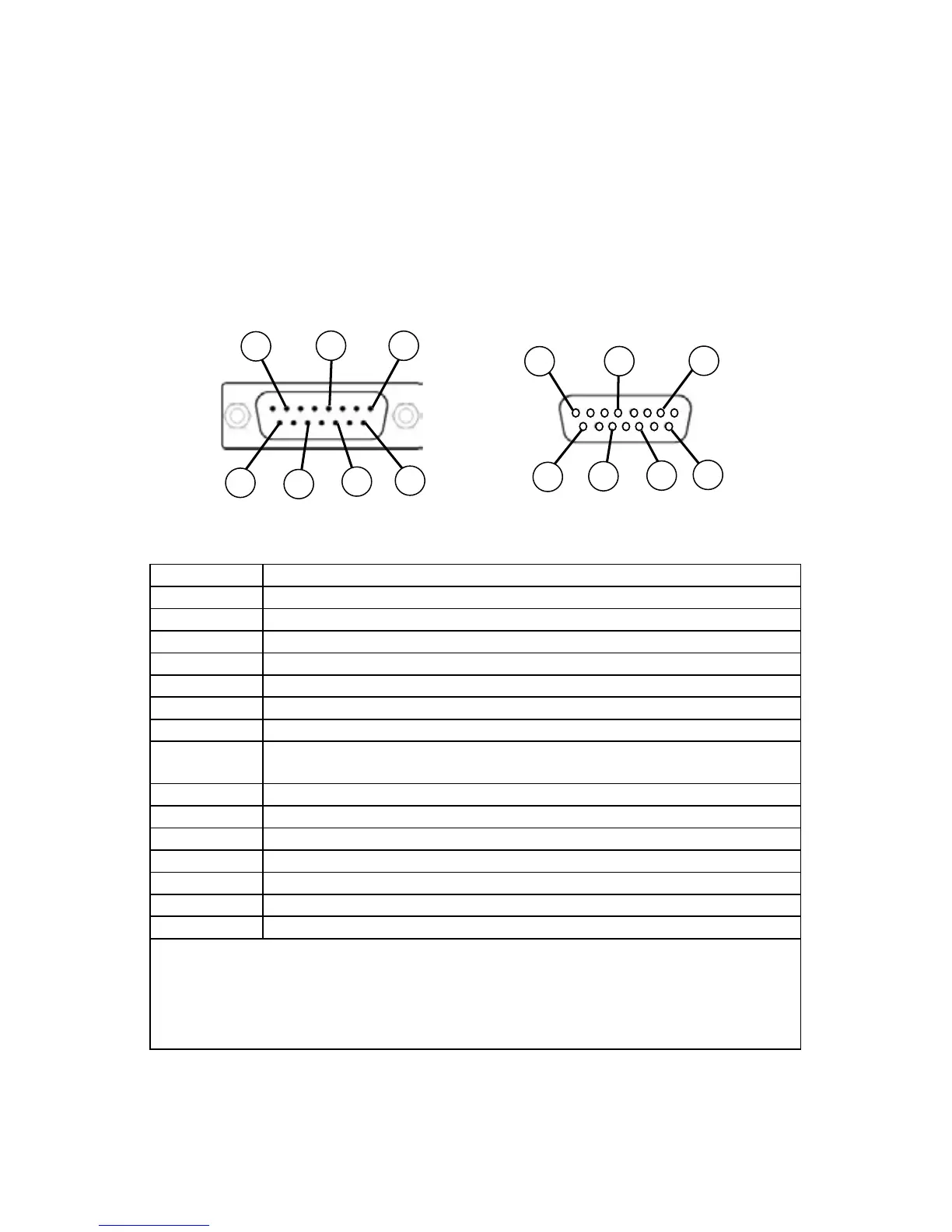
DB15 Pin-Outs
If your instrument was ordered with a DB15 connection, be sure to check the
Calibration Label on the device and reference the appropriate pin-out diagram.
DB15
Pin Number Function
1 Ground
2 Primary Analog Signal Output
3 Ground
4 N/C
5 Power Supply (+Vdc)
6 N/C
7 N/C
8
Analog Tare (meters — when grounded)
Analog Set-Point Input (controllers)
9 Power Supply Common
10 Ground
11 Secondary Analog Signal Output / xed 5.12Vdc
12 N/C
13 RS232 RX (receive) or RS485 –
14 Ground
15 RS232 TX (send) or RS485 +
Check your device’s calibration certicate and user manual for the actual electrical input/
output requirements, as all instruments are custom congured to some extent.
NOTE: Pins 1, 3, 9, 10, and 14 are connected together inside of the device and are
common grounding points.
N/C = Not Connected/Open (can be used for custom pin assignments – please consult factory).
The following pin-out chart describes the safest and generally compatible arrangement when
connecting a non-FMA-1600A DB15 wire to a DB15 equipped FMA-1600A. Not all features
may be available between brands, but the common denominators are featured in our DB15
offerings, along with some options for customization.
Male Connector Front View Female Connector Front View
8
15
13
11
9
2
5
8
15
13
11
9
2
5

 Loading...