17
1.2 Features of the UPS
! True On-Line structure provides reliable, regulated, transient-free AC power.
! High frequency designs to lower the size and weight.
! Micro-Processor Control can increase the reliability.
! High input power factor to meet the environmental concept for power saving.
! Self-Diagnostic function can provide information for troubleshooting reference.
! High capacity charger (10A) can rapidly charge the external battery bank.
! Cold-start provides start-up power even during ac utility blackouts.
! Sine wave regulated, low distortion inverter output.
! Load and Battery capacity indicators.
! Spike depression.
! Computer interface card(Novell+RS-232).
! Attractive office styling, easily accessible front panel controls.
1.3 Unpacking and Inspection
Unpack all items and save the packing materials in case you ever need to move the system. Inspect the contents of
the shipping carton as you unpack. If any of the following items are damaged or missing, contact your dealer
immediately.
! The UPS
! This user’s guide
! Two output power cord
! One input power cord
! One external battery wire (Long back-up time model only)
For the UPS with battery inside, a small plastic plate is inserted to the power switch to prevent it from being
accidentally switched on during shipment.
CAUTION- Do not remove the power switch security plate until the UPS has been properly inspected and
installed
1.4 The Front Panel
! (A) LINE: This green LED is on when the ac utility is normal, it is off when
in battery mode.
! (B) BYPASS: This yellow LED is on when the UPS is providing power
directly from the incoming ac utility through the bypass line.
! (C) INV: This green LED is on when the UPS power is from its inverter to
the load.
! (D) ALARM: This red LED is on when the UPS power is in a fault
condition. In the meantime, the alarm beeps continuously.
! (E) CAPACITY: This green LED bar indicates the load size in main mode
or the battery capacity in battery mode. In addition, it also indicates the
fault status when the ALARM red LED is on.
! (F) FULL LOAD: This yellow LED is on when the UPS is in full load
condition; please unplug the least critical equipment, such as a printer
etc.
! (G) OVERLOAD: This red LED is on when the UPS is in over load condition. Unplug some equipment immediately
until this LED is off. Otherwise the UPS will transfer to bypass mode after 20 seconds.
CAUTION- Ensure this LED is off within 20 seconds in battery mode. Otherwise the UPS will be turned off
because of no ac power in bypass.
! (H) MAIN SWITCH: Turn on the UPS by depressing this switch into “ | “ position and turn off the UPS by
depressing this switch into “
” position.
18
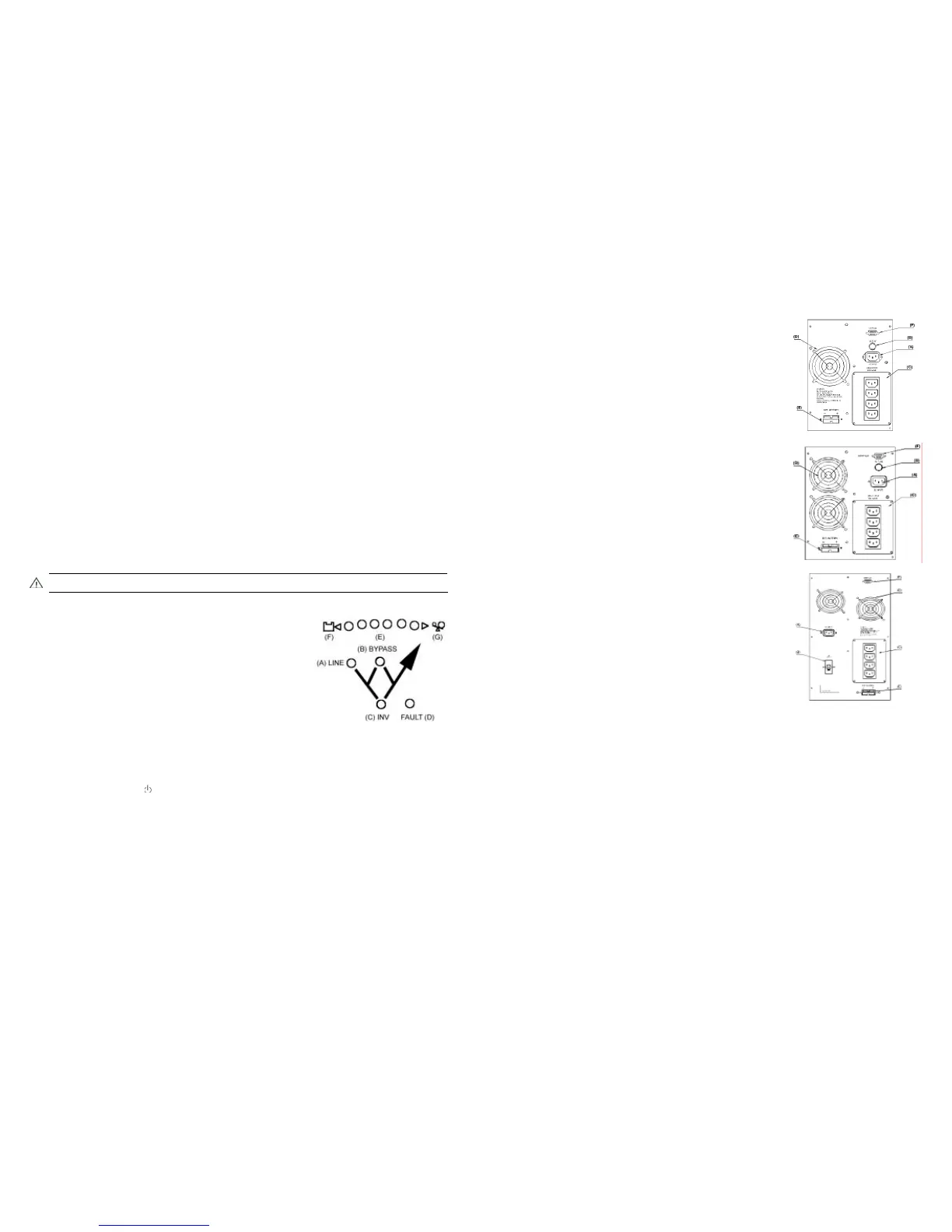
1.5 Rear Panel of OMEGA 1000
! (A)Power input socket : This socket is for the power cable of the
UPS connected to the ac utility.
! (B)Fuse holder: Contain the fuse of the UPS to protect the over current
from the incoming ac utility.
! (C)Power output sockets: This sockets are for the power cables of the
devices connected to the UPS.
! (D)Cooling fan: This fan is to prevent the UPS to overheat.
! (E)Battery socket: This socket is for the external battery cable of the
battery bank connected to the UPS.
! (F)Interface socket: This socket combines contact closure signals and
RS232 signals on one DB9 connector,
1.6 Rear Panel of OMEGA 2000
! (A)Power input socket : (for 230VAC Model)This socket is for the
power cable of the UPS connected to the ac utility Power input cable: (for
115VAC Model)The power cable of the UPS connected to the ac utility.
! (B)Fuse holder: Contains the fuse of the UPS to protect the over current
from the incoming ac utility
! (C)Power output sockets: This sockets are for the power cables of the
devices connected to the UPS.
! (D)Cooling fan: This fan is to prevent the UPS to overheat.
! (E)Battery socket: This socket is for the external battery cable of the
battery bank connected to the UPS.
! (F)Interface socket: This socket combines contact closure signals and
RS232 signals on one DB9 connector.
1.7 Rear Panel of OMEGA 3000
! (A)Power input socket : This socket is for the power cable of the
UPS connected to the ac utility.
! (B)Circuit breaker: Circuit breaker of the UPS to protect the over current
from the incoming ac utility.
! (C)Power output sockets: This sockets are for the power cables of the
devices connected to the UPS.
! (D)Cooling fan: This fan is to prevent the UPS to overheat.
! (E)Battery socket: This socket is for the external battery cable of the
battery bank connected to the UPS.
! (F)Interface socket: This socket combines contact closure signals and
RS232 signals on one DB9 connector
1.8 RS232 pin assignment and description
PIN# Description I/O
PIN 1 RS232 DTR, must keep in high state Input
PIN 2 Line fail, normally open, active close Output
PIN 3 N.C.
PIN 4 Common for pin 2,5
PIN 5 Battery low, normally open, active close Output
PIN 6 Two purposes on this pin Input
(1) Remote shut down, keep this pin high
(+5~+12V) for 3 sec will turn off the UPS
(2) RS232 Receiver Rx
PIN 7 Ground for pin 6,9
PIN 8 N.C.
PIN 9 RS232 Transmitter Tx Output
 Loading...