Table of Figures
Figure Description Page
1 I.E.C. Symbols .............................................................................. 1-2
2 Maximum Setpoint Temperature Limits ................................. 2-2
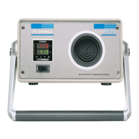
3 Front Panel ................................................................................... 3-1
4 Back Panel .................................................................................... 3-2
5 Menu Hierarchy Showing Factory Default Settings .............. 3-4
6 Programming Procedure ........................................................... 3-4
7 Heat Up / Cool Down Cycle Time Table ................................ 3-5
8 Connecting the BB702 to a Computer’s Serial Port ................ 4-1
9 Internal Reference Probe Connections ................................... 6-1
ii
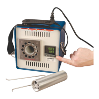
BB702 Blackbody Calibrator
Table of
Figures