P-28
P
1
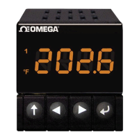
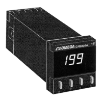
⁄16 DIN Autotune
Temperature Controllers
⻬ Auto/Manual Output Control
⻬ Field Replaceable Output Modules
Specifications
Accuracy: ±0.25% FS ±1°C (0.5°C in 0.1° resolution mode);
30-minute warm-up; see also linearized tolerance from
range chart
Control Stability: ±0.15% FS, typical
Sample Rate: 3 per second
Temperature Coefficient: ≤150 ppm/°C max
External Resistance: 100 Ω max
Cold Junction Compensation: 0.05°/degree ambient typical
Display: 3
1
⁄2 digit green LED; 10 mm (0.4") high; 1 or 0.1°
resolution; error indication, 3 deviation-from-setpoint indicators
Manual Reset: PD, proportional and on/off control;
set as degrees, deviation from setpoint is 1
Power: 24 Vac, 115 Vac, 230 Vac, ±15%, 50 to 60 Hz
Power Consumption: 6 VA
Output 1 Relay: SPDT relay, 5 A @ 250 Vac
Output 2 Relay: SPDT relay, 3 A @ 250 Vac
DC Pulse Output: Non-isolated 5 Vdc Pulse for driving
external dc solid state relay
Common Mode Noise Rejection: 140 dB, 240 Vac, 50/60 Hz
Normal Mode Noise Rejection: 60 dB, 50 Hz
Ambient Operating Range: 4 to 50°C (40 to 122°F)
Dimensions: 48 H x 48 W x 13 mm D bezel
(1.89 x 1.89 x 0.5"); 115 mm (4.5") depth behind panel;
154 mm (6.1") with triac voltage or current output
Panel Cutout: 45 mm
2
(1.772");
1
⁄16
DIN
Weight: 0.38 kg (0.84 lb)
OMEGACARE
SM
extended warranty program is available for models
shown on this page. Ask your sales representative for full details
when placing an order. OMEGACARE
SM
covers parts, labor, and
equivalent loaners.
Input Linearized Range Linearized
Type (Units are °F/°C Switchable) Tolerance
32 to 1470°F 0 to 800°C 1°C/2°F
32 to 1999°F 0 to 1200°C 1°C/2°F
-199 to 500°F -199 to 250°C 2°C/4°F
32 to 1100°F 0 to 600°C 1°C/2°F
32 to 572°F 0 to 300°C 5°C/9°F
572 to 1999°F 300 to 1600°C 2°C/4°F
32 to 572°F 0 to 300°C 5°C/9°F
572 to 1999°F 300 to 1600°C 2°C/4°F
1000 to 1999°F 500 to 1800°C 6°C/11°F
32 to 1999°F 0 to 1200°C 1°C/2°F
L (J DIN) 32 to 1470°F 0 to 800°C 1°C/2°F
-199 to 750°F -199 to 400°C 0.5°C/0.9°F
To Order (Specify Model Number)
Model No. Input Output 1 Output 2
CN9110AT 209 R R Relay –
CN9111A 230 Relay Relay
CN9112A 230 Relay Pulse
CN9120A 209 Pulse –
CN9121A 230 Pulse Relay
CN9122A 230 Pulse Pulse
CN9131A 293 1 A SSR Relay
CN9141A 293 4 to 20 mA Relay
CN9151A 293 0 to 10 Vdc Relay
CN9210A 209 Relay –
CN9211A 230 Relay Relay
CN9212A 230 Relay Pulse
CN9220A 209 Pulse –
CN9221A 230 Pulse Relay
CN9222A 230 Pulse Pulse
CN9231A 293 1 A SSR Relay
CN9241A 293 4 to 20 mA Relay
CN9251A 293 0 to 10 Vdc Relay
Model No.T Description
BT Dual relay, field installable module
BD9021AT Pulse/relay, field installable module
BD9031AT 1 A SSR and relay,
field installable module
BD9041A
†
4 to 20 mA and relay,
field installable module
BD9051A
†
0 to 10 Vdc and relay,
field installable module
BD9010AT Relay output board
BD9012AT Relay/pulse field installable module
BD9022AT Dual pulse field installable module
Replacement Output Modules
Input Types and Ranges
3-wire
RTD
T/C,
2-wire
RTD
†
To order “230 Vac” powered boards, add suffix “-230V” to model
number, no additional charge.
CN9000A Series
Starts at
$
209
CN9110A, $209.
MOST POPULAR MODELS HIGHLIGHTED!
115 V Models
Only
Comes complete with operator’s manual, mounting bracket and wiring terminals.
115 Vac models are UL recognized. UL not available for 230 Vac models.
To order units with “230 Vac” power, add suffix “-230VAC” to model,
no additional charge.
To order units with “24 Vac” power, add suffix “-24VAC” to model,
no additional charge.
Ordering Examples: CN9121A, autotune controller, pulse output
(output 1) and relay output (output 2),
OCW-2
US
For Complete Product
Information Visit
omega.com/cn9000a
WWW.100Y.COM.TW WWW.100Y.COM.TW WWW.100Y.COM.TW
WWW.100Y.COM.TW WWW.100Y.COM.TW WWW.100Y.COM.TW
WWW.100Y.COM.TW WWW.100Y.COM.TW WWW.100Y.COM.TW
WWW.100Y.COM.TW WWW.100Y.COM.TW WWW.100Y.COM.TW
WWW.100Y.COM.TW WWW.100Y.COM.TW WWW.100Y.COM.TW
WWW.100Y.COM.TW WWW.100Y.COM.TW WWW.100Y.COM.TW
WWW.100Y.COM.TW WWW.100Y.COM.TW WWW.100Y.COM.TW
WWW.100Y.COM.TW WWW.100Y.COM.TW WWW.100Y.COM.TW
WWW.100Y.COM.TW WWW.100Y.COM.TW WWW.100Y.COM.TW
WWW.100Y.COM.TW WWW.100Y.COM.TW WWW.100Y.COM.TW
WWW.100Y.COM.TW WWW.100Y.COM.TW WWW.100Y.COM.TW
WWW.100Y.COM.TW WWW.100Y.COM.TW WWW.100Y.COM.TW
WWW.100Y.COM.TW WWW.100Y.COM.TW WWW.100Y.COM.TW
WWW.100Y.COM.TW WWW.100Y.COM.TW WWW.100Y.COM.TW
WWW.100Y.COM.TW WWW.100Y.COM.TW WWW.100Y.COM.TW
WWW.100Y.COM.TW WWW.100Y.COM.TW WWW.100Y.COM.TW
WWW.100Y.COM.TW WWW.100Y.COM.TW WWW.100Y.COM.TW
WWW.100Y.COM.TW WWW.100Y.COM.TW WWW.100Y.COM.TW
WWW.100Y.COM.TW WWW.100Y.COM.TW WWW.100Y.COM.TW
WWW.100Y.COM.TW WWW.100Y.COM.TW WWW.100Y.COM.TW
WWW.100Y.COM.TW WWW.100Y.COM.TW WWW.100Y.COM.TW
WWW.100Y.COM.TW WWW.100Y.COM.TW WWW.100Y.COM.TW
WWW.100Y.COM.TW WWW.100Y.COM.TW WWW.100Y.COM.TW
WWW.100Y.COM.TW WWW.100Y.COM.TW WWW.100Y.COM.TW
WWW.100Y.COM.TW WWW.100Y.COM.TW WWW.100Y.COM.TW
WWW.100Y.COM.TW WWW.100Y.COM.TW WWW.100Y.COM.TW
WWW.100Y.COM.TW WWW.100Y.COM.TW WWW.100Y.COM.TW
WWW.100Y.COM.TW WWW.100Y.COM.TW WWW.100Y.COM.TW
WWW.100Y.COM.TW WWW.100Y.COM.TW WWW.100Y.COM.TW
WWW.100Y.COM.TW WWW.100Y.COM.TW WWW.100Y.COM.TW
WWW.100Y.COM.TW WWW.100Y.COM.TW WWW.100Y.COM.TW
WWW.100Y.COM.TW WWW.100Y.COM.TW WWW.100Y.COM.TW
WWW.100Y.COM.TW WWW.100Y.COM.TW WWW.100Y.COM.TW
WWW.100Y.COM.TW WWW.100Y.COM.TW WWW.100Y.COM.TW
WWW.100Y.COM.TW WWW.100Y.COM.TW WWW.100Y.COM.TW
WWW.100Y.COM.TW WWW.100Y.COM.TW WWW.100Y.COM.TW
WWW.100Y.COM.TW WWW.100Y.COM.TW WWW.100Y.COM.TW
WWW.100Y.COM.TW WWW.100Y.COM.TW WWW.100Y.COM.TW