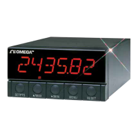
SECTION 1 INTRODUCTION
1.1 Description.............................................................................1-1
1.2 Features.................................................................................1-1
1.3 Available Models....................................................................1-2
SECTION 2 UNPACKING .........................................................................2-1
SECTION 3 SAFETY CONSIDERATIONS
3.1 Safety Considerations............................................................3-1
SECTION 4 PARTS OF THE METER
4.1 Front of the Meter ..................................................................4-1
4.2 Rear of the Meter...................................................................4-3
SECTION 5 SETUP
5.1 Conditions Requiring Disassembly........................................5-1
5.2 Assembly/Disassembly Opening ...........................................5-1
5.2.1 Safety Precaution/Product ID Label ......................................5-4
5.2.2 Main Board Power Jumpers ..................................................5-5
5.2.3 Printed Circuit Board(s) Installation .......................................5-6
5.2.4 How to Access Jumpers ........................................................5-7
5.2.5 Panel-Mount Assembly ........................................................5-11
SECTION 6 JUMPER POSITIONS
6.1 Introduction............................................................................6-1
6.2 S1 Jumper Positions for Readrate and
Unipolar or Bipolar Input(s)....................................................6-1
6.3 S2 Jumper Positions for Input Range....................................6-1
6.4 Jumper setting(s) for Sensor Excitation.................................6-3
6.4.1 Jumper setting(s) for Sensor Excitation ac-powered unit ......6-3
6.4.2 Jumper setting(s) for Sensor Excitation dc-powered unit ......6-5
SECTION 7 SIGNAL AND POWER INPUT CONNECTIONS
7.1 Introduction............................................................................7-1
7.2 Signal Input Connections.......................................................7-1
7.3 Connecting Main Power.........................................................7-3
SECTION 8 METHODS FOR SCALING THE METER TO DISPLAY IN
ENGINEERING UNITS
8.1 Introduction............................................................................8-1
8.2 Strain Gage (Bridge) Input, programming the meter for a
desired Display ......................................................................8-1
8.3 Voltage Input (Non-Ratiometric), programming the meter
for a desired Display...........................................................8-15
8.4 Current Input, programming the meter for a desired Display ....8-28
i
Table of Contents

 Loading...