Do you have a question about the Omega DRST-CM and is the answer not in the manual?
Device is for hazardous voltages; ignoring warnings can cause injury or damage.
Connect only when fixed; operations on disconnected device under ESD safe conditions.
Repair of the device must only be done by Omega A/S.
Explains symbols for manual reference, CE mark, and double insulation.
Instructions for checking the device upon receipt and unpacking.
Guidelines for operating the device in suitable environmental conditions.
Requirements for qualified personnel and device condition during mounting.
Procedures for calibration and adjustment using safe tools and instruments.
Method for cleaning the device when it is disconnected.
Specific safety requirements for installation in Zone 2 hazardous areas.
Limits Omega's liability if manual instructions are not followed.
Enables programming of system DRST devices via the display.
Provides Modbus RTU communication over RS485.
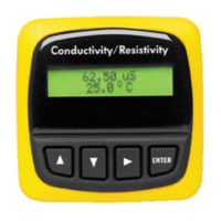
Allows monitoring of process values directly from the built-in display.
Offers high galvanic isolation of 2.5 kV to the host unit.
Features a shielded RJ45 connector for Modbus communication.
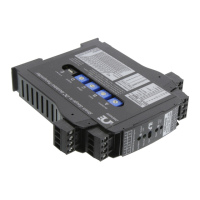
Adds Modbus RTU RS-485 communication to DRST units.
Converts various sensor and analog signals to Modbus communication.
Converts signals from/to I.S. classified areas to Modbus network.
Allows easy configuration of parameters via Modbus or front display menu.
Display can show process signal, simulate output, and indicate errors.
Includes full DRSL-DISPLAY features for programming and diagnostics.
Supports Modbus RTU protocol over RS-485 communication wiring.
Features multidrop half-duplex connection via shielded RJ45.
Provides 2.5 kVAC galvanic isolation between serial wiring and DRST units.
Modbus parameters are configured via the DRST-CM display.
Specifies mounting requirements for Zone 2 / Div 2 hazardous areas.
The DRST-CM is movable between DRST units, allowing configuration saving.
Allows protection of programmed parameters with a user-defined password.
Menu option to rotate display 180 degrees and invert button functions.
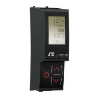
DRST-CM is a detachable display for programming and monitoring on DRST fronts.
Describes the four-line LCD display and its content capabilities.
Details the pinout for the RJ45 Modbus connector (RS485 A/B, GND).
Information for ordering the DRST-CM Communication Enabler.
Information for ordering the DRSL-DISPLAY Configmate interface.
Specifies operating temperature, storage, humidity, and protection degree.
Details dimensions, weight, and connection type.
Covers power consumption and isolation voltage ratings.
Details immunity to EMC phenomena like bursts.
Lists signal/noise ratio, update rate, signal type, and serial protocol details.
Covers Modbus mode, devices per line, data rates, baud detection, parity, stop bits, and addressing.
Lists relevant approvals like EMC, LVD, UL, Marine, and Ex certifications.
Illustrates a typical Modbus RTU network setup.
Shows Modbus RTU setup in a Zone 2 / Class 1, Div 2 hazardous area.
Depicts a network configuration using Modbus TCP/IP.
Explains the master-slave architecture of Modbus communication.
Details Modbus RTU, its use over RS485, and common speeds.
Describes the components of a Modbus RTU message (Address, Function Code, Data, Error Check).
Lists common Modbus function codes supported by the DRST-CM.
Explains the role of Data fields and Error Checks (CRC) in Modbus.
Specifies the maximum number of registers that can be read or written at once.
Configuration option for automatic baudrate detection (YES/NO).
Lists the various baudrates supported by the DRST-CM.
Available parity modes: Even, Odd, or None.
Option to select 1 or 2 stop bits for communication.
Configurable response delay from 0 to 1000 ms.
Defines the valid range for Modbus slave addresses (1-247).
Indicates that parameters are saved in non-volatile memory.
Recommendation for using a 120 Ohm resistor for line termination.
Illustrates the menu structure for configuring the DRST-CM locally.
Provides descriptions for various helptext codes used in menu navigation.
Diagram for enabling or disabling Modbus communication.
Flowchart for resetting Modbus parameters to default settings.
Diagram for rotating the device display and function of buttons.
Displays default settings for baud rate, parity, stop bits, address, and response delay.
Continues the routing diagram for Modbus settings and general navigation.
Details the 13-month warranty period and exclusions.
Lists actions that will void the warranty, such as mishandling or modification.
States Omega's liability limitations and exclusions for damages.
Advises against using products in nuclear, medical, or human applications.
Provides instructions for warranty and repair return procedures.
| Brand | Omega |
|---|---|
| Model | DRST-CM |
| Category | Transmitter |
| Language | English |