6
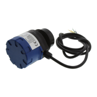
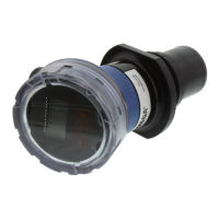
How to demount System DRST
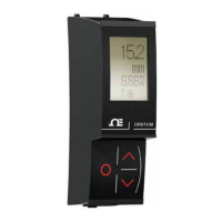
3
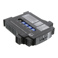
Section 3 - Communication Enabler
• Programming display for system DRST devices
• Modbus RTU protocol interface over RS485
• Monitor process value from the built-in display
• High 2.5 kV isolation to host unit
• Shielded RJ45 Modbus connector on top
Section 4 - Applications
• The DRST-CM detachable display adds Modbus RTU RS-485 serial communications to all current and future
DRST units.
• The unit converts a wide array of sensors and analog device signals measured by the system DRST, like uni- and
bipolar mA and voltage signals, potentiometer, Lin. R, RTD and TC, to a Modbus communication line signal.
• When mounted on a system DRST device any signal coming from or going to I.S. classified area, like AI, AO, DI
and DO signals, can be converted to a Modbus network.
• All individual unit operating parameters can easily and quickly be configured by using the Modbus
communication or by using the front display menu.
• The easily readable DRST-CM display can be used to read the process signal, simulate the output signal, indicate
sensor errors and internal module errors.
Section 5 - Technical Characteristics
• DRST-CM has full DRSL-DISPLAY functionality for unit programming, process signal monitoring and
diagnostics handling.
• Modbus RTU protocol is supported using a serial RS-485 communication wiring.
• Multidrop half-duplex connection via shielded RJ45 connector.
• High safe galvanic isolation of 2.5 kVAC between the serial wiring and the connected system DRST units.
• Modbus parameters such as address, baud rate, stop bit(s), and parity bit are configured from the DRST-CM
display, which also stores parameters.
Section 6 - Mounting / Installation / Programming
• Mounting in Zone 2 / Div 2.
• The DRST-CM can be moved from one device to another. The individual system DRST unit configuration of the
first transmitter can be saved and downloaded to subsequent transmitters.
• Programmed parameters can be protected by a user-defined password.
• When mounted on devices that are installed upside down, a menu item allows the display on the DRST-CM to be
rotated 180o and the up/down buttons to switch function.
 Loading...