4
TOP
RIGHT
SIDE
BACK
BOTTOM
FRONT
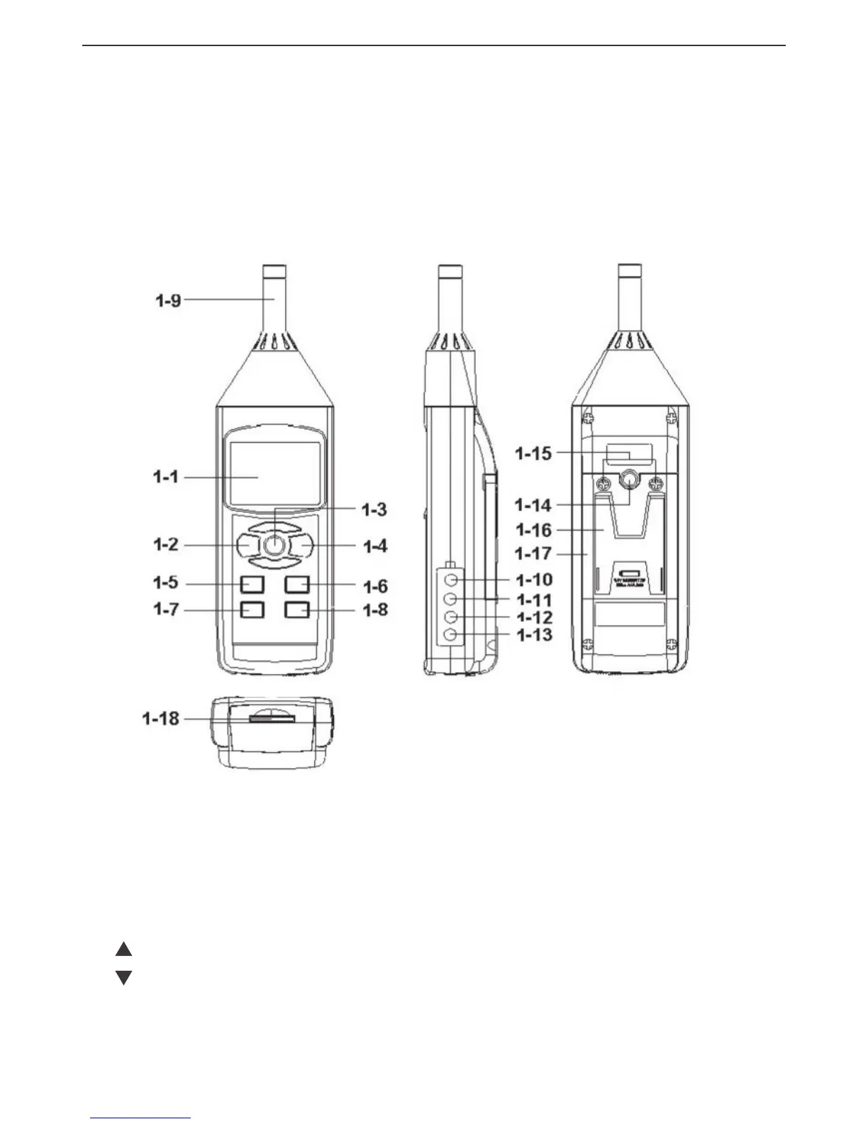
1-1 Liquid-crystal display
1-2 POWER/ESC button
1-3 HOLD/NEXT button
1-4 REC/ENTER button
1-5
button
1-6
button
1-7 SET button
1-8 LOGGER button
1-9 Microphone
1-10 AC output terminal
1-11 Calibration screw
1-12 RS-232 output jack
1-13 Socket for 9VDC
AC adapter
1-14 Tripod attachment nut
1-15 Battery compartment
cover screws
1-16 Kickstand
1-17 Battery compartment
cover
1-18 SD card socket
OPERATING INSTRUCTIONS
WHAT’S IN THE CASE
The HHSL402SD comes fully assembled in a hard carrying case along with a sound wind
shield ball, a 2 GB SD memory card and this user’s manual.
Figure 1 shows all of the controls and indicators on the front, right side, back and bottom of
the HHSL402SD. Familiarize yourself with the positions and functions of these controls,
indicators and connectors before moving on to the setup
procedure.
F
ig. 1. The HHSL402SD’s controls and indicators and other physical features
 Loading...