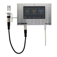
The iServer 2 Series offers a range of virtual chart recorders and webservers designed for collecting and displaying live sensor readings through a web-based user interface or by integrating with an Omega Link Cloud account. These devices are versatile, accepting either an Omega Link Smart Probe or two thermocouples, depending on the specific model.
Function Description:
The iServer 2 acts as an edge controller, capable of autonomous independent decision-making to generate local alarms or provide control outputs based on sensor inputs. It features a fully configurable alarm system within its web UI, allowing users to set events and thresholds for notifications via email or text. Omega Link compatible devices, including the iServer 2, can be integrated into an existing Omega Link Ecosystem for remote data access by adding the iServer 2 to an Omega Enterprise Gateway account and then connecting that account to the Omega Link Cloud.
Important Technical Specifications:
Models and Sensor Types:
- iS2-THB-B (Basic): Smart Probe compatibility, 1x USB port.
- iS2-THB-ST (Standard): Smart Probe compatibility, 4.3" LCD, 1x USB Port, Digital I/O and Relays.
- iS2-THB-DP (Deluxe Probe): Smart Probe compatibility, 4.3" LCD, 1x USB Port, Digital I/O and Relays, Power over Ethernet (PoE).
- iS2-THB-DTC (Deluxe Thermocouple): 2x Thermocouple ports, 4.3" LCD, 1x USB Port, Digital I/O and Relays, Power over Ethernet (PoE).
Interfaces:
- Ethernet (RJ45): 1x port (PoE available on qualifying models).
- Supported Protocols: TCP, UDP, SNMP, SNTP, ARP, ICMP, DNS, HTTP, Telnet.
- Omega Link Smart Probe: 1x M12 8-Pin port.
- Thermocouple: 2x ports (available on qualifying models).
- Digital I/O and Relays: 2x RS232/RS485 1.5 A @ 30 V DC.
- LED Indicators: 100 BASE-T, Network Link and Activity, DHCP, Internet.
- Alarm I/O: Two contact inputs TTL 0.5; one open collector output 150 mA @ 30 V DC.
- Sample Rate: 8 samples/second max.
Memory Capacity and Sample Rate:
The internal 11 GB memory can store data for varying durations depending on the sample rate and number of active sensors:
- 1 second (max): 4 years (2 active sensors), 2 years (4 active sensors).
- 5 seconds: 24 years (2 active sensors), 12 years (4 active sensors).
- 10 seconds: 40 years (2 active sensors), 20 years (4 active sensors).
Mechanical:
- Dimensions (Base Device): 101.6 mm L x 155.6 mm W x 330 mm H (4 in. L x 6.13 in. W x 12.99 in. H), not including bracket and M12 connector.
- Material: Stainless Steel.
- Display: LCD 32 mm L x 93.5 mm W.
- Weight: 655 g (1.44 lbs.), including battery.
Power:
- Power Input: 9 to 12 V DC.
- Consumption: 4 W.
- AC Power Adapter (Included) Nominal Output: 12 V DC @ 1.5 A.
- Power Over Ethernet (PoE): IEEE 802.3AF, 44 V – 49 V, Power Consumption under 10 W. Input: 100 to 240 V AC, 50/60 Hz.
- Back-Up Battery: 9 V DC, alkaline. Provides 96 hours at 5 seconds recording intervals and 1 second reading with two connected probes.
Environmental:
- Operating Temperatures (iServer 2 Unit): 0 to 60°C (32 to 140°F).
- Operating Temperatures (Battery): -18 to 55°C (-0.4 to 131°F).
- AC Power Adapter: 0 to 40°C (32 to 104°F).
- Industrial Cable: -40 to 125°C (-40 to 257°F).
- Storage Temperature: -40 to 85°C (-40 to 185°F).
Usage Features:
Hardware Setup:
The iServer 2 can be wall-mounted or attached to a DIN rail. Wall-mounting screw holes are 2 ¾” (69.85 mm) apart. For Smart Probe models, a bracket and stand-off extenders are included to mount the probe 1 ½" away from the unit, recommended for accurate sensor readings. The physical reset button is located on the left side of the unit.
Sensing Device Setup:
- M12 Omega Link Smart Probe Connection: Smart Probes connect via an M12 connector, either directly or with an 8-pin extension cable. For proper operation, Smart Probes with Digital I/O (DIO) must have their Digital I/O set to "Active Low" using Omega's SYNC configuration software.
- Thermocouple Connection: The iS2-THB-DTC model accepts up to two thermocouples. Cold Junction Calibration is available for most thermocouple types (excluding R, S, and B) via the web UI. Users can configure Offset (b) and Gain (m) in the sensor channel settings to compensate for B-type thermocouple wire error.
- Digital I/O and Relays: Terminal block connectors are provided for Digital I/O and Relays. DI connections accept 5V (TTL) input, DO connections require external voltage (up to 0.5 amps at 60V DC), and Relays (R1, R2) support loads up to 1 amp at 30V DC. Grounding the unit is recommended when wiring these connections.
Powering the iServer 2:
All variants include a DC power supply, international adapters, and a 9V battery. PoE-enabled models can be powered via a network switch or PoE injector. The LED Status Indicator provides visual feedback on power, system boot, factory reset, internet connection, and firmware update status. A fully charged 9V battery provides up to 96 hours of backup power, logging up to 10,000 data points.
Connecting to a PC:
Three methods are available:
- DHCP Router Setup (Display Models only): Connect via RJ45 to a DHCP-enabled router. The assigned IP address appears on the device display.
- Direct to PC Setup with RJ45 Ethernet Cable: Connect directly to a PC. The MAC Address on the device label is used to access the web UI via
http://is2-omegaXXXX.local (where XXXX are the last 4 digits of the MAC address).
- Direct to PC Setup – Micro USB 2.0: Connect directly to a PC via micro-USB. The default static IP is 192.168.3.200. Administrator access may be required to change PC Network Properties.
Navigating the iServer 2 Web UI:
The web UI is accessed via a browser. The default username is "admin," and the password is on the device label.
- Gauge / Chart View: Displays live sensor readings in either a gauge or chart format. Users can adjust view ranges and secondary Y-axis sources in Chart View.
- Device Name and Sensor Firmware Information: The System tab allows configuring the device name and viewing firmware details. Users can check for and download firmware updates for Smart Probes directly from the web UI.
- Network Configuration: Users can configure IP Address, Netmask, and Gateway settings, choosing between DHCP or Static IP.
- Logging: Set automatic logging intervals, retrieve recorded data as .CSV files, and clear log data. The "Clear Log Data" button must be pressed before switching Smart Probe types to prevent data corruption.
- Events and Notifications Configuration: Configure alarm thresholds, triggers, and notification parameters for various events (System Error, Battery Level Warning, Probe Disconnection, etc.).
- Buzzer: Enable/disable audible alarms and select triggers.
- Relay 1 and Relay 2: Configure initial states (Normally Open/Closed), triggers, and display options for the two relays.
- Email: Set up email recipients, Heartbeat Interval (normal operation updates), and Alarm Interval (alarm notifications).
- Digital I/O: Configure Digital Inputs (enabled/disabled, initial state, display on homepage/log) and Digital Output (Active High/Low, display on homepage/log, latching).
- System Configuration: Control factory resets, firmware updates, and system time. The iS2-THB-DTC model allows selecting Single or Dual TC.
- Profile: Update username and password.
- Units: Configure displayed units of measure for various parameters (Weight, Pressure, Temperature, etc.).
- Channel Settings: Adjust Gain and Offset values, set display ranges, and define alarm triggers (High Low, Above, Below).
Adding to Omega Enterprise Gateway (OEG):
The iServer 2 can be added to OEG 2.4 in a non-internet environment. Two methods are available:
- DHCP Router Method: Connect the iServer 2 to a DHCP-enabled router.
- Static IP (Direct to PC) Method: Configure a static IP for the iServer 2 and the Windows PC running OEG.
iServer2 Modbus Holding Register Partition:
The device supports Modbus communication, with registers partitioned for channel readings (read-only), device meta-information (model, firmware, name), and configuration settings. NaN values indicate no measurements, disabled sensors, hardware failure, or out-of-spec readings.
Maintenance Features:
Firmware Updates:
Firmware for Smart Probes can be updated through the iServer 2 web UI or Omega's SYNC configuration software. It is crucial to download the firmware file first, then use the "Browse" and "Upgrade" functions. A factory reset will set the Digital I/O to Active Low by default.
Factory Reset:
Pressing and holding the reset button for 10 seconds will reset the iServer 2 to factory default, clearing all stored data and configuration. A factory reset or configuration reset while a Smart Probe is plugged in will clear any user-set probe configuration settings.
Troubleshooting:
The manual provides a table of error messages (OPEN, SHORT, RANGE, NAN/INVAL) and their descriptions to assist in diagnosing device issues.
Security:
The iServer 2 is designed for use in secure local-area networks (LANs). Exposing the device to public internet traffic through Port Forwarding or similar methods is cautioned against due to significant security risks.