3
Operation
3
SECTION 3 – OPERATION
3.1 – Measuring Temperature
Before starting to measure temperature, make sure the following check list is met:
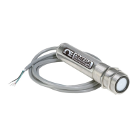
The power and output connections are made (Fig 2-1).
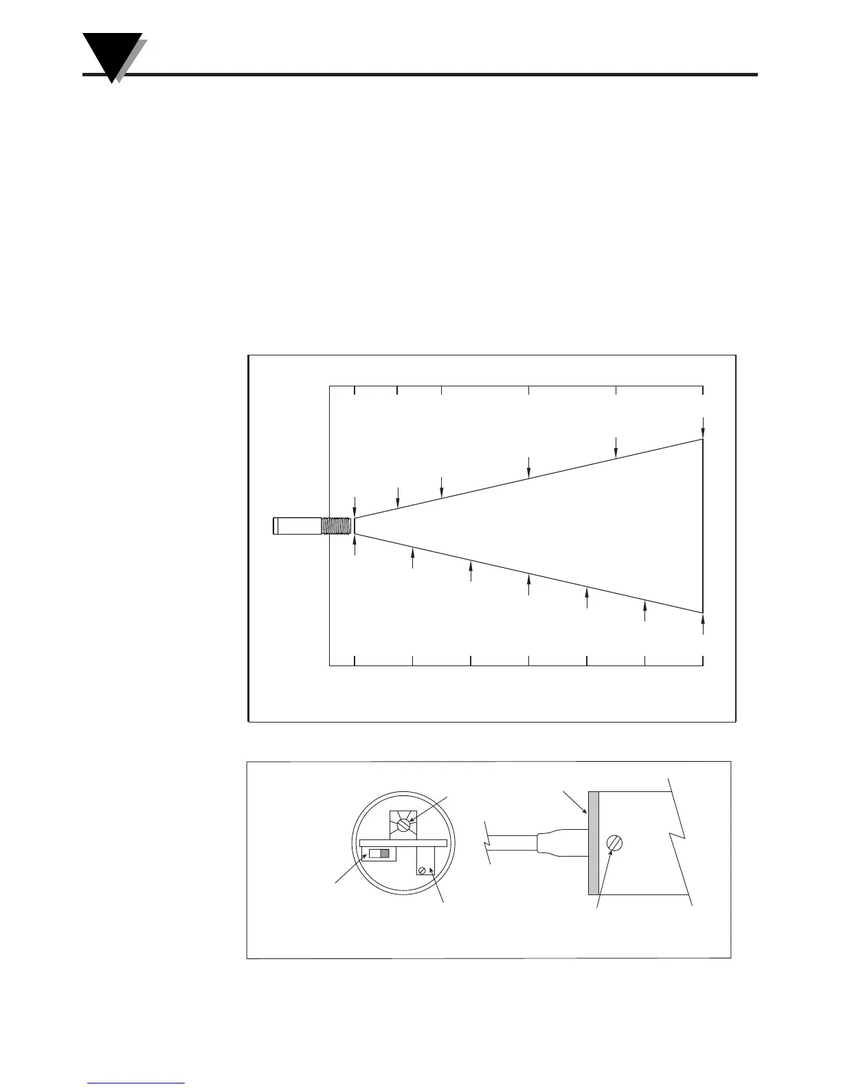
The target is larger than the optical field of view of the transmitter (Fig 3-1).
Use the Laser Sighting accessory (optional), to align the transmitter to the
center of the target area.
Remove the End Cap to get to the Emissivity Single Turn Pot (Fig. 3-2). Set
the Emissivity Pot based on the target surface. Then put back the End Cap.
Make sure the output load is within the product specification.
Figure 3-1. Optical Field of View
Figure 3-2. Location of Emissivity & Alarm Adjust and Alarm Switch
SPOT DIA.* (CM)
SPOT DIA.* (IN)
DISTANCE: SENSOR TO OBJECT (FT)
D:S = 10:1
1.6 cm@0
0
40
5.6
80
9.6
210
13.6
160
17.6
200
21.6
244
26
0.65"@0"
3.0"
1.75"
5.5"
7.8"
10.2"
8
6
4
21
0
DISTANCE: SENSOR TO OBJECT (CM)
* SPOT DIAMETER MEASURED AT 90% ENERGY
ALARM
SWITCH
1- REAL TIME
2- ALARM POSITION
ALARM
ADJUST
EMISSIVITY
ADJUST
REMOVE THE SCREW TO PULL OUT
THE END CAP. THE EMISSIVITY AND
ALARM ADJUST & ALARM SWITCH ARE
LOCATED ON THE MAIN PC BOARD.
END CAP
12
1.00
0.70
0.60 0.90
0.80
0.50
 Loading...