34
OPTIMA 120
WORK CYCLE
CICLO DI LAVORO
CONTROLLI PRELIMINARI GENERALI
Prima di cominciare il ciclo di lavoro, è necessario
verifi care le seguenti condizioni operative:
• l’allacciamento elettrico ad una rete di alimenta-
zione corrispondente alla tensione nominale della
macchina riportata sulla marcatura CE applicata al
basamento ed indicata nel capitolo “Identifi cazione
della macchina” del presente manuale d’uso &
manutenzione;
• l’allacciamento pneumatico ad un impianto di aria
compressa che sia in grado di fornire una pressione
nominale d’esercizio suffi ciente.
Il valore di pressione è di 6 bar, controllare sul
manometro del gruppo fi ltro riduttore lubrifi catore,
indicazioni descritte nel capitolo “Collegamento
pneumatico”del presente manuale d’uso & manu-
tenzione;
• l’allacciamento ad un impianto di aspirazione
che soddisfi le specifi che ed i requisiti descritti nel
capitolo “Collegamento aspirazione” del presente
manuale d’uso & manutenzione;
• l’effettiva chiusura e/o regolazione di tutti i ripari
ed il serraggio dei rispetttivi elementi di fi ssaggio.
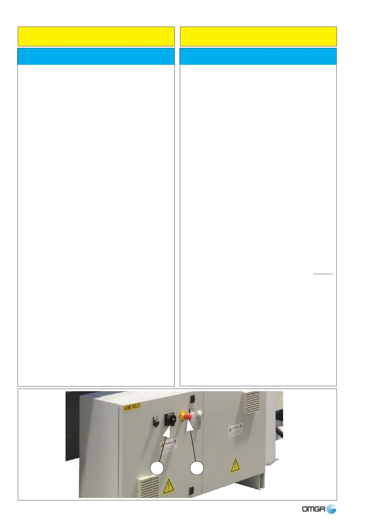
Verifi care inoltre che:
• l’interruttore/sezionatore (3) sia ruotato in posizione
tale da garantire la presenza di corrente;
• il pulsante a fungo (2) di EMERGENZA sia riar-
mato;
• le dimensioni dell’asta da tagliare siano idonee
alle capacità di taglio della macchina (consultare il
capitolo “Capacità di taglio” del presente manuale
d’uso & manutenzione);
• l’utensile sia esente da grasso e/o sporcizia, non
sia incrinato e/o saldato (il suo utilizzo è proibito);
• il senso di rotazione della lama sia corretto;
GENERAL PRELIMINARY CONTROLS
Before starting the work cycle, check the following
operating conditions:
• connection to a power supply that is compatible
with the machine’s nominal voltage displayed on the
CE marking applied to the base and indicated in the
chapter ‘Machine identifi cation‘ of this user manual.
• connection to a compressed-air system that can
provide suffi cient nominal operating pressure.
To required operating pressure (3 bar) as explained
and check on gauge of lubricator reduction gear fi lter
unit, (see the chapter on “Pneumatic Connections”
of this user manual);
• that the compressed-air connection meets the
specifi cations set out and the requirements specifi ed
in chapter “Dust Extraction Connections” of this
user manual;
• all guards are shut and correctly adjusted and the
respective fi xing items are tightened.
Also check that:
• the switch/circuit breaker (4) is turned to a vertical
position in order to ensure current.
• the EMERGENCY switch (2) is reset;
• the dimensions of the workpiece to be cut are
suitable for the machine’s cutting capacities (see the
chapter on ‘Cutting capacity’ of this user manual);
• the tool are free of grease and/or dirt, not
cracked and/or welded (greasy, dirty or cracked
tool) must not be used);
• blade rotation direction is correct;
23
 Loading...