© OMICRON 2024 Page 13 of 25
2. Make sure that the connection to ground at the far end of the power line is not removed during the
complete test procedure.
3. In addition to the grounding switch, ground the cable at the near end, using a grounding set
consisting of three cables rated for the maximum short-circuit current possible on the line. Now the
circular current is split between the near grounding switch and the grounding set.
4. Open the near grounding switch in order to measure the entire circular current via the grounding set.
5. Then measure the current in each of the three phases of the grounding set with a common current
clamp and note the values. Depending on the geometry of the line the values for the currents could
slightly differ.
6. Close the grounding switch again.
7. Disconnect the grounding set from the power cable and ground.
Alternatively, the circular currents can also be measured directly at the grounding switch by using a
Rogowski coil or other suitable measuring devices. Then the grounding set is not needed for the
measurement of the circular currents. One advantage of the measurement is the possibility to detect contact
problems at the grounding switch. If one of the measured currents is much lower than the others, this could
indicate a contact problem at the grounding switch of that respective phase (this of course only refers to the
measuring method using a Rogowski coil).
Death or severe injury caused by high voltage or current.
Make sure all the contacts at the grounding switch are in good condition (free of
oxidation). Note: If no voltage is measured on any of the phases, this does not
necessarily mean that the grounding switch is working properly!
The estimated voltage can now be calculated according to equation Eq. 1 or 2 be
low by using the highest of
the three measured currents.
Note: If line length is measured in kilometers use Eq. 1. For miles use Eq. 2.
=
∙ 2 ∙ 0.4 ∙
Ω
km
∙ max
(
1
,
2
,
3
)
(Eq. 1)
=
∙ 2 ∙ 0.64 ∙
Ω
mi
∙ max
(
1
,
2
,
3
)
(Eq. 2)
Maximum allowed voltage U
est
: 20 V.
Note: If the calculated voltage U
es
t
exceeds 20 V, the measurement cannot be performed, since the current
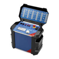
output of COMPANO 100 is not designed for driver higher voltages! If this is the case, please consider the
following options:
• Try to reduce the interference from parallel cables by
a) reducing the load flow on parallel cables,
b) de-energizing parallel systems.
• Perform the measurements at another time, when load flow is lower.
If none of the above is successful, consider using CPC 100 + CP CU1 + CP GB1 as alternative
measurement solution, which can be used for voltages up to 500 V.

 Loading...