© OMICRON 2024 Page 14 of 25
3.3 Third criterion: Measured open-line voltage
After the estimation of the open-line voltage, CP GB1 can now be connected to the cable under test, in order
to measure the actual open-line voltage and verify the estimation.
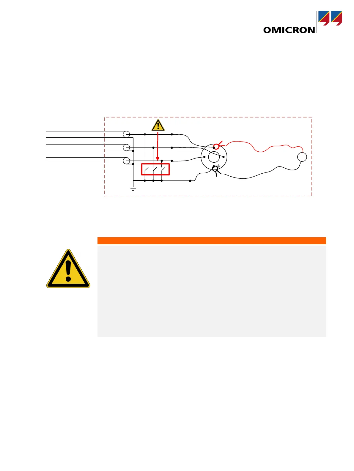
Set up a voltmeter according to Figure 5. The Kelvin clamps on the grounding box must be
connected to the phase where the highest circular current has been measured and ground.
In the example in Figure 5 the Voltmeter is connected to L1 and ground.
Figure 5: Measuring the coupled voltage with a voltmeter.
To measure the open-line voltage, perform the following steps:
1. Make sure the grounding switch is closed!
Death or severe injury caused by high voltage or current possible.
Connecting grounding socket clamps of one type to a grounding point of another
type is highly dangerous on both the connection of the grounding set to the CP GB1
and the connection of the CP GB1 to the grounding point in the substation. The 16
to 20 mm grounding socket clamp is designed and tested for fault currents up to
26.5 kA, the 25 mm (1 inch) grounding socket clamp for fault currents up to 30 kA,
both for a maximum duration of 100 ms.
Make sure to use the proper grounding socket clamp and that the grounding
stud is in good condition, clean and free of oxidation!
On locations where higher fault currents are possible than the grounding
socket clamps are designed for, the CP GB1 must not be used!
2. Connect the CP GB1 to ground near the place where the connection to the power line is made. Use
the cable
delivered with the CP GB1 and the proper grounding socket clamp.
3. Connect the cables of the grounding set used for estimating the open-line voltage (see 3.2 Second
criterion: Estimated open-cable voltage.) to the GB1.
4. Connect the other ends of the grounding set to the three phases of the power cable.
While connecting the grounding set to the power
cable, the grounding switch must be closed!