4
Advanced Partial Discharge Measuring System MPD 600
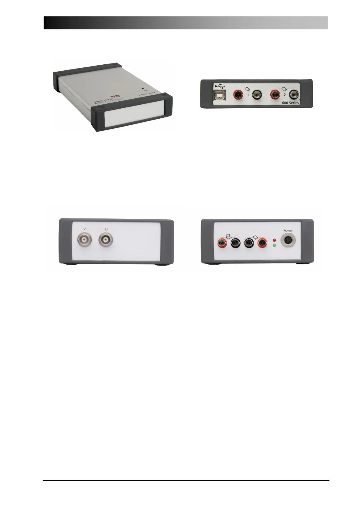
Figure 2: MCU 502 fiber optics controller (top and rear view)
• Connect the fiber optics controller to the Notebook Computer using a standard USB
cable (USB 2.0).
Figure 3: MPD 600 Acquisition Units (front and rear view)
• Connect the MPD 600 Acquisition unit to the fiber optics controller using fiber optical
cables.
See wiring diagram on next page for details. Please observe that TX (transmit) is always
connected to RX (receive) and vice versa.
• Connect the power supply (or battery) to the MPD 600 Acquisition unit.
The red LED starts flashing indicating that the acquisition unit is ready for operation.
• Connect the external coupling unit CPL 542, also referred to as “quadripole” or
measuring impedance.
Use two short BNC cables and connect the PD and V outputs of the coupling unit
CPL 542 to the PD and V inputs of the acquisition unit MPD 600.
• Connect the coupling unit CPL 542 to a high voltage coupling capacitor (or RFCT,
measuring tap, other Sensor). Always remember to keep the cable(s) as short as
possible.
• Connect the Notebook PC’s power supply and switch it on.