5
Advanced Partial Discharge Measuring System MPD 600
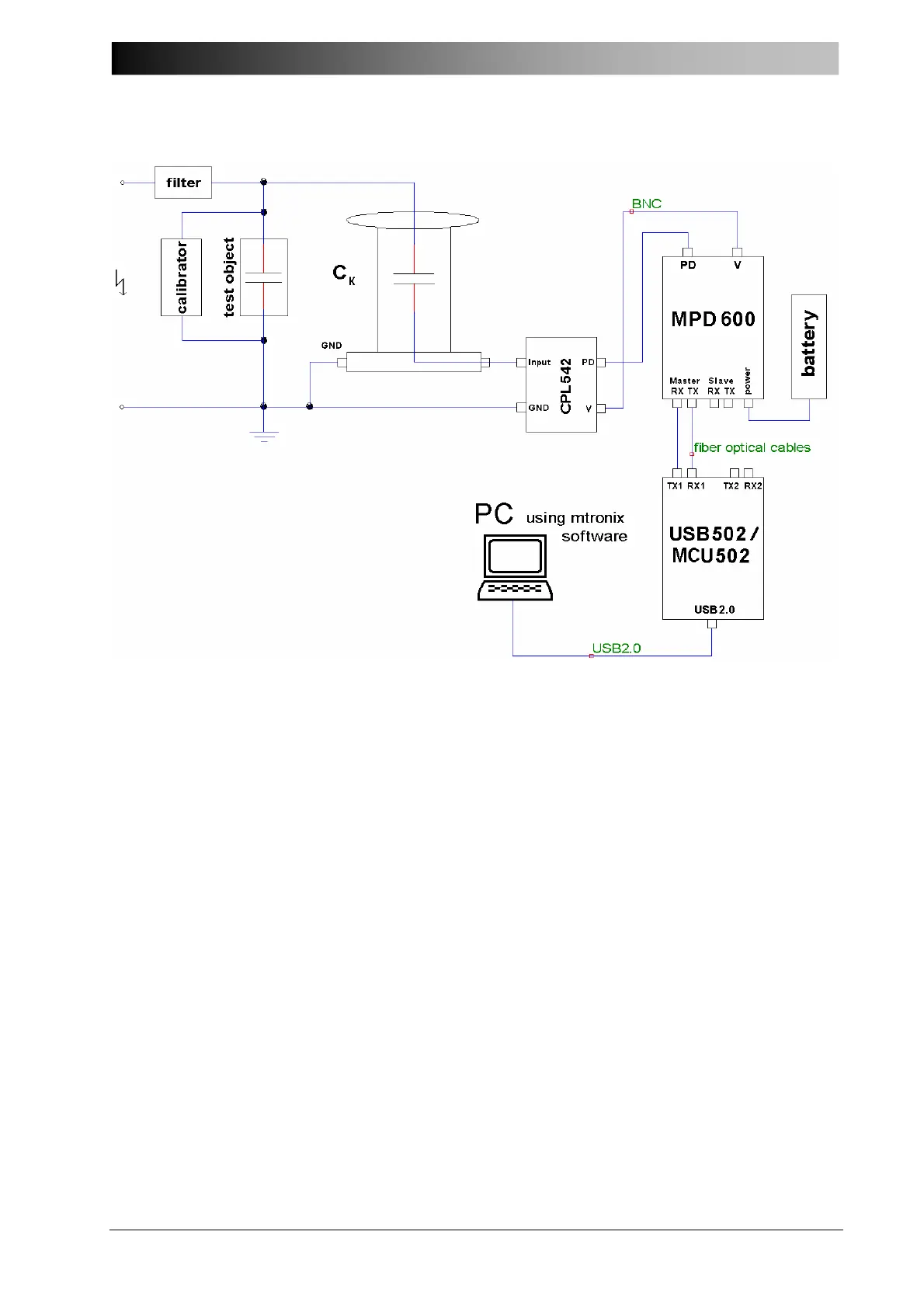
Figure 4 Connecting the MPD 600 PD measuring system
Please substitute the battery pack with a power supply if desired.
Always remember to keep all cables in the signal path as short as possible. The MPD 600
acquisition unit is small and should be placed as close as possible to the coupling capacitor and
test object.
Fiber optical cables connect the test set-up via the fiber optics controller (MCU 502) to the
notebook PC and provides complete safety and electrical insulation. Fiber optical cables used
with the MPD 600 system may be up to 2 km in length between each unit.
IMPORTANT: The calibrator shown in figure 4 has to be disconnected before turning on the high
voltage supply.