4
DMAN-xxxx-xx
www.omnexcontrols.com
call toll free: 1-800-663-8806
SW 2
J1939 Setup
STATUS
LINK
ESTOP
CAN 1
CAN 2
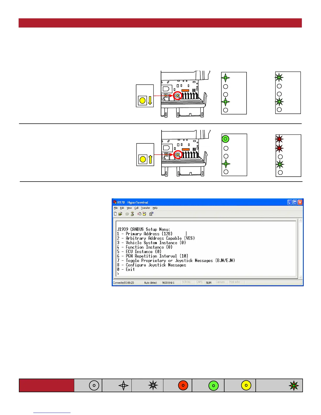
A. Press and hold [SW 2] on the
R170’s front panel. The (Status)
and (CAN 1) lights will flash
GREEN slowly.
B. Continue to hold [SW 2] until the
(Status) and (CAN 1) lights begin to
flash GREEN quickly (5 seconds).
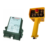
A menu will be displayed in your communications program as shown below.
B
CAN 2
CAN 1
ESTOP
LINK
STATUS
C. When this occurs, release the button
to enter J1939 CANBUS Setup Mode.
D. If the [SW2] button is held for more
than 10 seconds, the (Status) and
(Link) LED indicators will flash RED
quickly.
You may set the R170’s J1939 Primary Address using option 1 in the menu. The default primary address is 128,
which corresponds to the J1939 OEM address.
As shown in Table 1, the following fields can be defined by the user using the CAN setup menu:
• Arbitrary Address Capable (option 2)
• Vehicle System Instance (option 3)
• Function Instance (option 4) and
• ECU Instance (option 5)
Figure 1: CANbus Setup Menu
CAN 2
CAN 1
ESTOP
LINK
STATUS
CAN 2
CAN 1
ESTOP
LINK
STATUS
D
SW 2
A
C
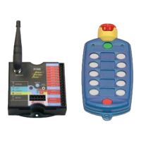
The R170 uses J1939 over CAN bus to communicate with the other devices in the system. Certain J1939 specific
parameters may be configured by the user by entering the J1939 CANBUS Setup Mode. To enter J1939 CANBUS
Setup Mode, proceed as follows:
NOTE: Connect the R170 to the PC via a serial cable and program using HyperTerminal—Refer to Appendix C for details
Light Legend
Solid
Slow
Flash
Fast
Flash
Red
Light
Green
Light
Alternating Red
& Green Light
Yellow
Light
NOTE: this menu may be different
depending on the firmware option
provided with your unit.