© 2010 Omnicell, Inc. OmniTT/AnesthesiaTT Installation and Service Guide/67-2024 Rev D
Electronics Tray 1-5
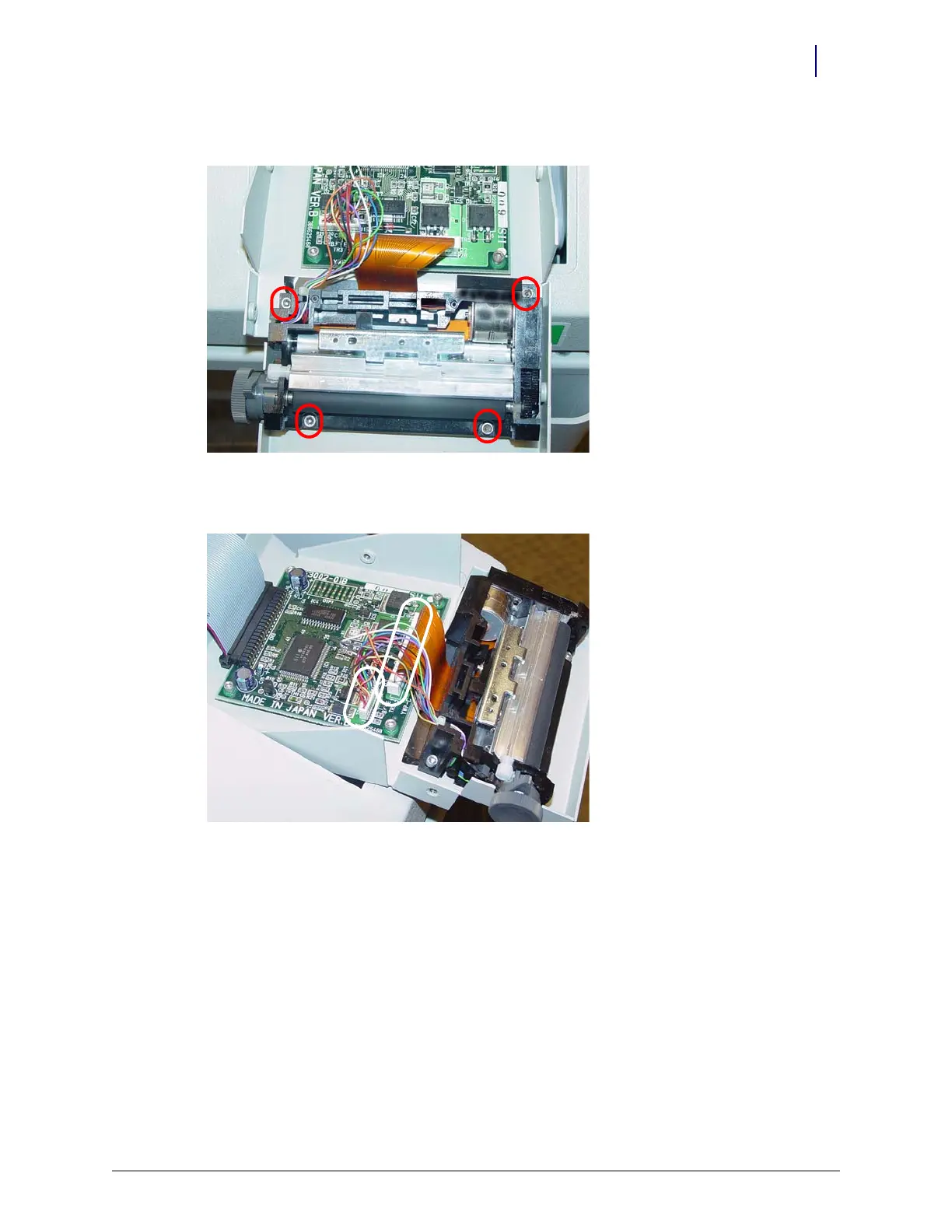
Removal Procedure
6. Remove the four screws that secure the lower assembly to the frame.
Figure 1-8. Remove the Screws that Secure the Lower Assembly
7. Disconnect the printer ribbon cable and the printer data cables from the printer PC board.
Figure 1-9. Remove the Printer Ribbon Cable and the Printer Data Cable