25
The installation technician is responsible for selecting a cable with
the appropriate length and cross section.
Step 5. Create an Installation Map
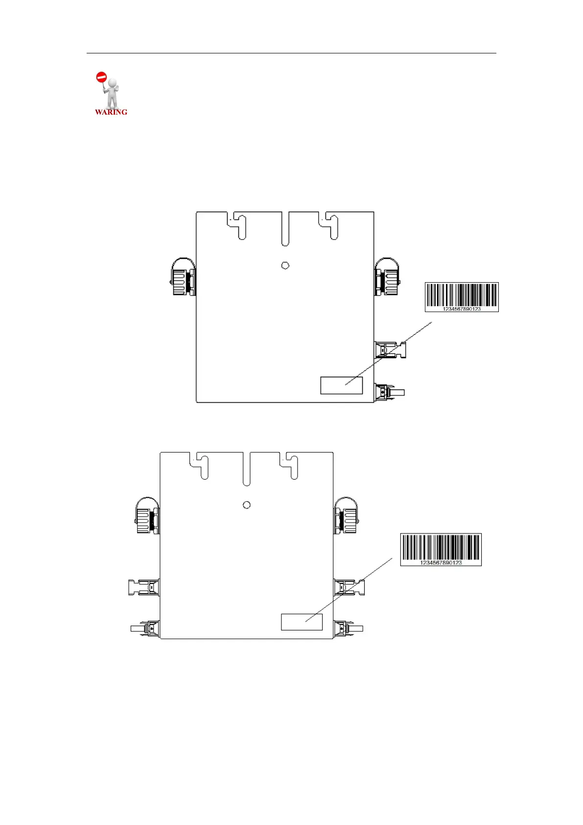
Peel the removable serial number label from each micro-inverter. The position of the
label is shown as below. The DC inputs of SMP600 are identified by A and B. The left
input is A and the right one is B, shown as above.
Fig.32. Serial Number Label (SMP300)
Fig.33. Serial Number Label (SMP600)
Affix the serial number label to the respective location on the installation map (found
in the Appendix of this manual).
 Loading...