20
4. AC CONNECTION
5. VOLTAGE SELECTOR
Make sure that the indication corresponds to the available voltage.
6. AUDIO OUT-SOCKETS
The music-signal of these sockets is analogue. Connect the output to the respective input of your mixer.
7. DIGITAL OUT-SOCKET
The music-signal of this socket is digital. Connect the output to the respective input of a digital amplifier for
example.
8. REMOTE CONTROL
Connect the controller via these plugs. Make sure that you connect the player Unit 1 to the controller Unit 1
and the player Unit 2 to the controller Unit 2.
4.3 Controller
In order to design this user manual as structured as possible, only one side of the controller is described.
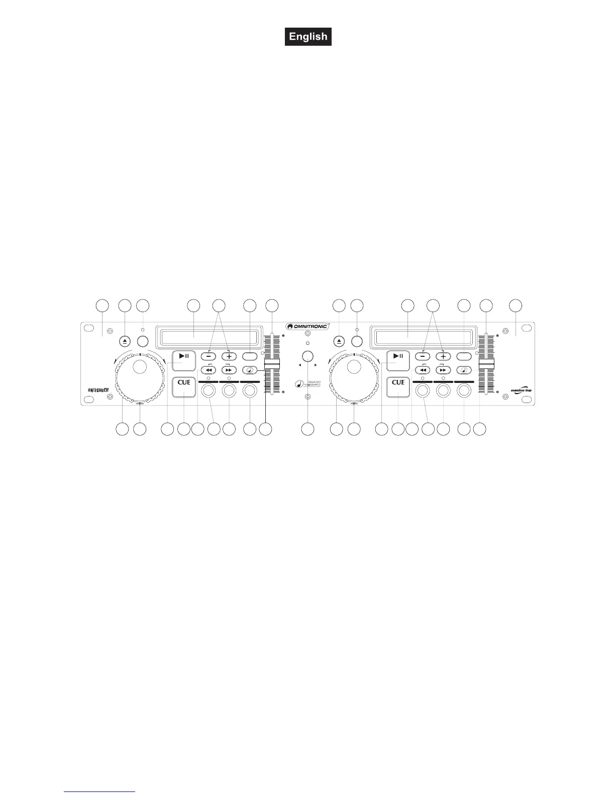
Frontpanel:
1 23 4
5 6 789
11 12 13
141516 17
10 3 4
5 6 789
11 12 13
141516
10
18 18
_
_
_
_
– –
SEAMLESS LOOP SEAMLESS LOOP
LOOP IN/FLY CUE LOOP IN/FLY CUE
PGM PGM
SGL SGLTIME TIME
LOOP OUT/EXIT LOOP OUT/EXITRELOOP RELOOP
LOOP
ON
LOOP
ON
OPEN/CLOSE OPEN/CLOSE
1 2
PITCH PITCH
8% 12% 16% 8% 12% 16%
8% 12% 16% 8% 12% 16%
RELAY
TRACK TRACKMAIN TEMPO MAIN TEMPO
PITCH BEND PITCH BEND
REV- REV-
FWD+ FWD+
SHUTTLE/SCAN SHUTTLE/SCANJOG/SEARCH JOG/SEARCH
0% 0%
PITCH PITCH
TRACK M S F TRACK M S F
CDP-500
DUALCD-PL AYER
1. SECTION UNIT 1
The left part of the controller is designed for controlling the left CD-player (1).
2. SECTION UNIT 2
The right part of the controller is designed for controlling the right CD-player (2).
3. OPEN/CLOSE BUTTONS
Via the Open/Close-buttons, you can open and close the respective CD-tray.
4. DISPLAY
LCD-display for displaying the different modes and functions. Please refer to the explanations under 6.3
LCD-display.
5. SHUTTLE-WHEEL
Playback-mode:
Via the Shuttle-wheel, you can quickly scan forwards and backwards. Turn the Shuttle-wheel to the right in
order to scan forwards and turn it to the left in order to scan backwards. The further you turn the Shuttle-
wheel the higher the scanning-speed.
Pause-mode:
In the pause-mode, the current frame is repeated as soon as you turn the Shuttle-wheel.
6. JOG-WHEEL
Playback-mode:
Via the Jog-wheel, you can temporarily adjust the playback-speed by +/- 16 %.
Pause-mode:
In the pause-mode, the current frame is repeated as soon as you turn the Jog-wheel.