00039532.DOC, Version 2.0
17/20
channel via headphones. This button lights to
immediately indicate that the channel is monitored.
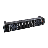
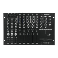
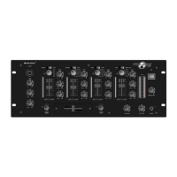
21 Channel faders
Level controls for channel 1-5.
22 Time control for the talkover function
djusts the attenuation response time in case o
microphone announcements.
23 Power indicator
Lights up when the unit is powered on.
18 Control CUE/PGM
For crossfading the monitoring signal for the headphone
output: Left position CUE: the pre fader level of the input
channel of which the CUE button is pressed is monitored.
Right position PGM: the music program currently playing
is monitored ahead of the output controls OUT 1-3. In
mid-position, a mixed signal consisting of pre fader level
and of the current music program can be heard.
19 Level controls for the master outputs
20 Buttons CUE
Buttons for pre fader listening of the corresponding
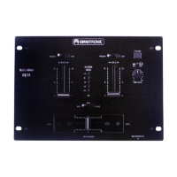
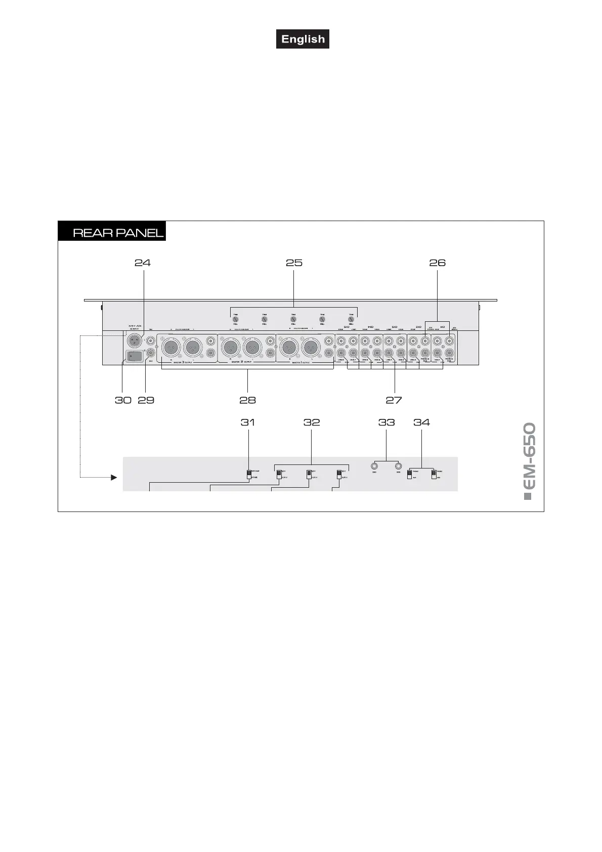
24 AC input
Plug in the supplied power unit here.
25 Gain controls
Trimming controls for adjusting the input amplification o
channel 1-5 (from right to left).
26 PHONO inputs
Stereo inputs PHONO (RCA) for channel 2 and channel 3
for connecting turntables with magnetic system.
27 LINE inputs
Stereo inputs LINE (RCA) for channel 1 to 5 fo
connecting units with line level outputs (e. g. CD/MP3
player).
28 Master outputs
Stereo master outputs (optionally 3-pin XLR, bal. or RCA)
for connecting an amplifier or other units with line level
inputs (e.g. a further mixer, active speakers):
outputs MASTER 1 for master channel ZONE 1,
outputs MASTER 2 for master channel ZONE 2,
outputs MASTER 3 for master channel ZONE 3.
29 REC(ORD) output
Stereo output REC (RCA) for connecting a recording unit.
The recording level is independent of the position
of the output controls OUT 1-3.
30 Power on/off
Press this button to turn the unit on and off. When
powered on, the POWER indicator on the front panel
lights up.
31 Selector switch RECORD
Switches the microphone channels at the output
REC(CORD) on and off. Upper position WITH MIC:
recordings with microphone signals. Lower position NO
MIC: recordings without microphone signals.
32 Level selector switch
Switches the level at the master outputs between 0.75 V
and 1.5 V.
33 GND (ground terminals)
Ground clamping screws for turntables connected to
channel 1 and channel 2.
34 Input selector switches
Switches the phono inputs to line inputs.