00039532.DOC, Version 2.0
18/20
5 INSTALLATION
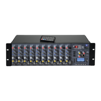
5.1 Rack installation
Install the unit on a plane surface or in your rack. For 19" (483 mm) rack installation, 2 units are required.
When mounting the unit into the rack, please make sure that there is enough space around the device so
that the heated air can be passed on. Steady overheating will damage your device. You can fix the unit with
four screws M6 in the rack.
5.2 Connections
Switch off the mixer prior to connecting any units or to changing any existing connections.
1 Connect the stereo audio sources to the corresponding RCA jacks of channels 1-5 (white jack = LEFT;
red jack = RIGHT):
- Connect units with line level output (e. g. CD/MP3 player) to the jacks LINE
- Connect turntables with magnetic system to the jacks PHONO. If your turntable is equipped with a
separate ground lead, connect it to the clamping screw GND.
2. You can connect two microphones via XLR plug or 6.3 mm plug to the microphone inputs MIC 1 and
MIC 2 on the front panel.
3. For connecting amplifiers or other subsequent units with line level inputs (e.g. a further mixer, active
speakers), three stereo master outputs are available for each PA zone: a balanced XLR output and an
unbalanced RCA output: outputs MASTER 1 for master channel ZONE 1, outputs MASTER 2 for master
channel ZONE 2, outputs MASTER 3 for master channel ZONE 3.
Via the assignment switches 1-3, the input channels can be switched to the individual master channels
as desired.
4. For sound recordings, two recording units can be connected: one unit to the output REC(ORD) on the
front panel and a further unit to the output REC(ORD) on the rear panel. The recording level is
independent of the position of the output controls OUT 1-3. Via the assignment switches REC(ORD)
SELECT 1-3, the master channels 1-3 can be individually switched to the REC(ORD) output on the front
panel. At the REC(ORD) output on the rear panel, the microphone signals can be switched on and off
with the selector switch RECORD.
5. The input channels can be monitored via stereo headphones. Connect the headphones to the 6.3 mm
jack PHONES on the front panel.
6. Connect the power supply unit to the AC input of the EM-650 and the mains plug to a mains socket.
Use the unit only with the supplied power unit. Always disconnect the mains connector when you wish to
change connections, move the unit to a different place or if it is not used for a longer period.
6 OPERATION
Prior to switching on, turn the output controls OUT 1-3 to minimum to avoid damage to the hearing by a
volume which is too high when switching on. Switch on the unit with the power switch. The power indicator
on the front panel lights up. Switch on the connected units. After operation, switch off the unit with the power
switch.
6.1 Level control of channels 1-5
1 Set all gain controls and tone controls to mid-position.
2 Use the input selector to select the input to which the audio source is connected.
3 Feed an audio signal (test signal or music piece) to the channel. Switch off the units which are to play on
the other channels or set them to pause.
4 Advance the channel fader to approx. 2/3 of its maximum.
5 Use one of the assignment switches (LED lights) to switch the input channel to the master channel which
is to be used for level control: button 1 for master channel ZONE 1, button 2 for master channel ZONE 2,
button 3 for master channel ZONE 3.
5. Advance the master control of the master channel used to approx. 2/3 of its maximum.
6 Via the LED level indication of the master channel used, control the level of the input channel with its
gain control. An optimum level control is obtained if level values in the 0 dB range are shown at average
volume. If the red LEDs of the level indication light up, there is an overload of the channel.
7 Repeat the steps for the other connected input channels as described above.