00039532.DOC, Version 2.0
16/20
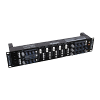
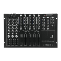
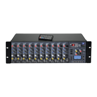
4.2 Operating elements and connections
1 Microphone inputs MIC 1 and MIC 2
Input jacks (bal.) for connecting microphones via XLR o
6.3 mm jack plug.
2 Assignment switches 1-3
ssignment switches 1-3 (with LED), to assign the
microphone channels MIC 1 and MIC 2 individually to the
three master channels:
button 1 pressed: microphone channel switched to ZONE 1,
button 2 pressed: microphone channel switched to ZONE 2,
button 3 pressed: microphone channel switched to ZONE 3.
3 Level controls with PEAK LED
Level controls for the microphone channels MIC 1 and
MIC 2. If the LED lights permanently, the corresponding
channel is overloaded.
4 Tone controls
3-way equalizers for the microphone channels MIC 1 and
MIC 2: HIGH, MID, BASS.
5 LED level indicators
10-digit LED level indicators for the microphone channels
MIC 1 and MIC 2 within the range of -20 dB to +9 dB.
6 Microphone channel on/off
On/off switches (with LED) for the microphone channels
MIC 1 and MIC 2. When the button is pressed (LED
lights), the corresponding microphone is switched on.
7 Level control for the talkover function
djusts the attenuation level in case of microphone
announcements.
8 Talkover on/off
On/off switch (with LED) for the talkover function. With
the button is pressed (LED lights), the levels of the
channels 1-5 are automatically attenuated - depending on
the controls LEVEL and TIME - when announcements are
made with the microphone.
9 Assignment switches 1-3
ssignment switches 1-3 (with LED), to assign the inputs
channels 1-5 individually to the three master channels:
button 1 pressed: input channel switched to ZONE 1,
button 2 pressed: input channel switched to ZONE 2,
button 3 pressed: input channel switched to ZONE 3.
10 Input selectors
For selecting the input source for channels 1-5. The LEDs
will verify which input is active.
11 Signal indicator for channels 1-5
12 Tone controls
3-way equalizers for the master channels: HIGH, MID,
BASS.
13 LED level indicators
10-digit LED level indicators for stereo master signal
within the range of -20 dB to +9 dB.
14 Assignment switches 1-3
ssignment switches 1-3 (with LED), to assign the maste
channels 1-3 individually to the REC(ORD) output:
button 1 pressed: ZONE 1 switched to REC(ORD),
button 2 pressed: ZONE 2 switched to REC(ORD),
button 3 pressed: ZONE 3 switched to REC(ORD).
15 REC(ORD) output
Stereo output REC (RCA) for connecting a recording unit.
The recording level is independent of the position of the
output controls OUT 1-3.
16 Headphones input
6.3 mm jack (bal.) for connecting stereo headphones
(min. impedance 8 Ω).
17 Level control for the headphone output