00072954.DOC, Version 1.0 15/20
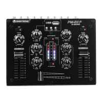
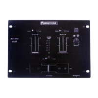
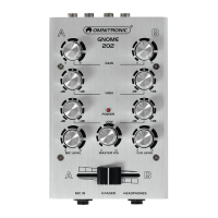
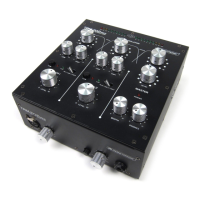
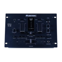
4. OPERATING ELEMENTS AND CONNECTIONS
1 Input selector switches
For switching the rear inputs of channels 1 and 2
from line to phono input.
2 Gain controls
Adjust the input amplification for channels 1 and 2.
3 Tone control for the DJ microphone
4 Channel faders for channels 1 and 2
5 Level control for the DJ microphone
6 Talkover on/off
On/off switch for the talkover function. With the button
engaged (red LED lights), the levels of the channels 1
and 2 are automatically attenuated by 20 dB when
announcements are made with the DJ microphone.
7 Crossfader
For crossfading between channel 1 and channel 2.
8 Output level LED meter
Switchable
6-digit LED meter for the stereo master
signal or the monitor signal within the range of -10
dB to +5 dB. In monitor mode, the prefader signal of
channel 1 is displayed on the left side of the level
meter and the prefader signal of channel 2 on the
right side.
9 Selector switch LED level display
• Switch disenganged: indication of the master level
• Switch engaged: indication of the monitor level of
channels 1 and 2 (red LED lights)
10 Control CUE MIXING
Fades between channel 1 and channel 2 for the
headphones output.
11 Level control for the headphones output
12 Master level control
13 USB port
USB port for connecting a USB storage device.
The MP3 player’s signal is directly sent to the
master outputs; it is not affected by the TALKOVER
switch and cannot be routed to the headphones
output.
14 Button [►II]
For switching between play and pause.
15 Buttons [] and []
• Short actuation: for title selection
• Long actuation: for fast forward/reverse
16 Level control for the MP3 player