Set value Description
3
Sets the value obtained by adding the analog voltage input (input terminal [AI1]) and analog
current input (input terminal [AI2](AII)) as the frequency reference.
5 Sets the frequency reference via the analog voltage input (input terminal [AI2](AIV)).
• Analog input can adjust the input signal by gain and bias. (Refer to 7-3-2 Analog Input Adjustment
Function on page 7-38.)
•
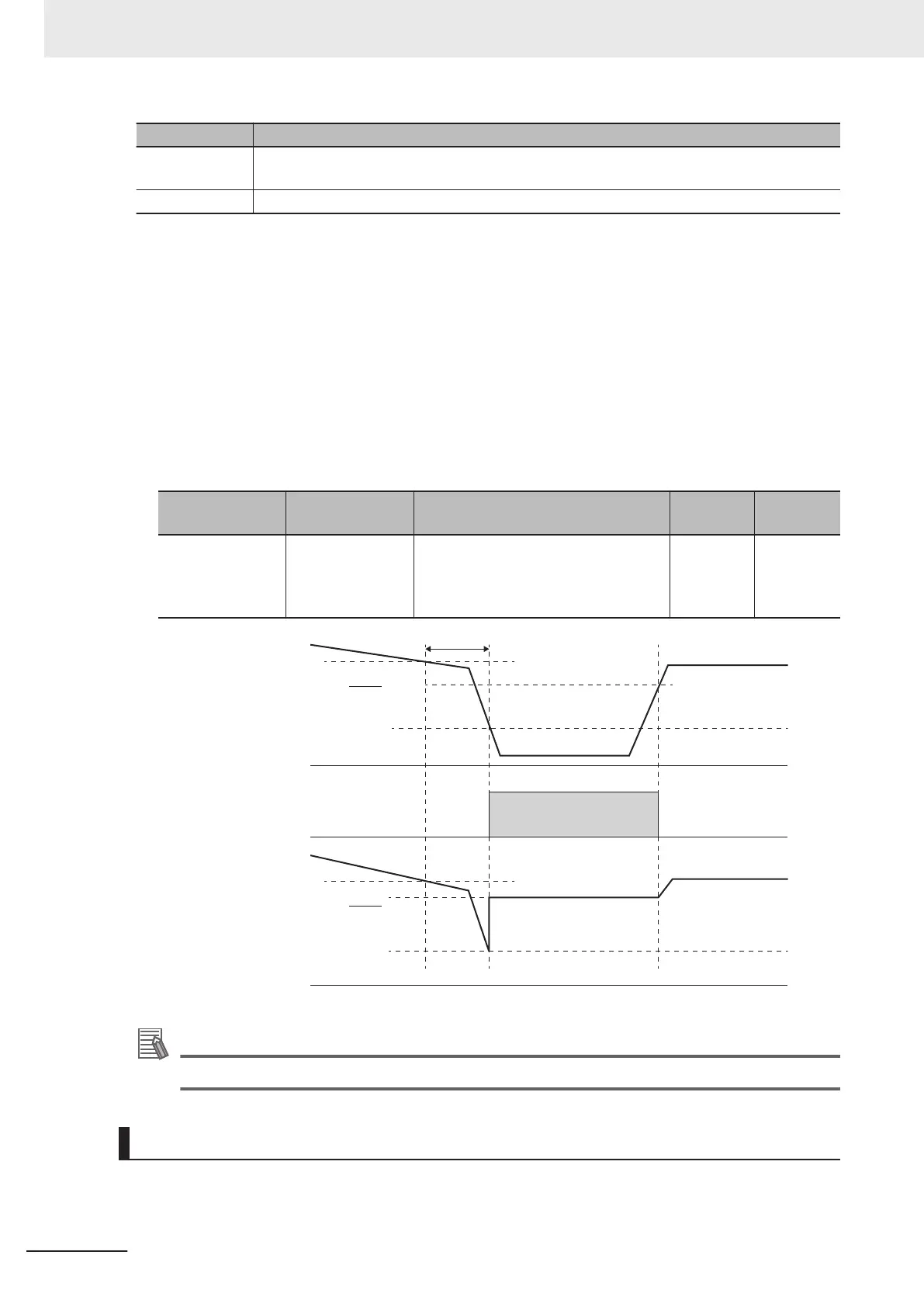
Behavior when the analog signal is disconnected can be set at analog reference loss detection.
Analog Reference Loss Detection
When the analog frequency reference falls to 10% or lower of the frequency reference for 400 ms,
the wiring of the analog frequency reference is judged to have become disconnected, operation is
continued at the frequency of the ratio set at E65 for the frequency setting value, and the analog
input reference loss detection “33: REF OFF (analog input reference loss)” terminal is turned ON.
When the frequency setting value returns to the value set at E65 or higher, it is judged that the dis-
connection has been restored, and operation is performed at the legitimate frequency setting.
Parameter No. Function name Data
Default
data
Unit
H193
Analog Reference
Loss Detection
Operation Selec-
tion
0: Decelerate to stop
20% to 120% 999%
999: Cancel
0 -
Analog
frequency setting
Regular frequency
setting
ON
f1
f1
f1 ×
E65
100
f1 × 0.1
400ms
f1 × 0.1
Command loss
detection
“REF OFF”
Frequency setting
(internal data)
f1 ×
E65
100
Additional Information
• With the frequency reference via analog input, select only linear acceleration/deceleration.
UP/DOWN Control (Frequency Reference Selection (F01/C30) = “7”)
• Refer to 7-9-10
UP/DOWN control
on page 7-1
19.
5 Basic Settings
5-30
M1 Series Standard Type User's Manual (I669)