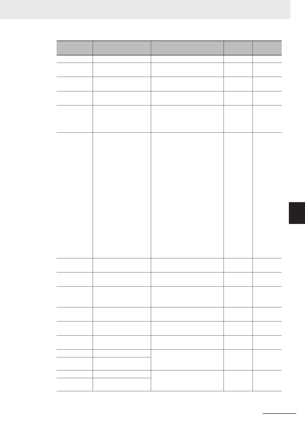
Parameter No. Function name Data
Default da-
ta
Unit
d204 Position Loop Gain 2 0.1 to 300.0 1.0 time
d205
Position Loop Gain
Switch Frequency
0.0 to 590.0 Hz 0.0 Hz
d206
Electronic Gear Denomi-
nator
1 to 65535 1 -
d207
Electronic Gear Numera-
tor
1 to 65535 1 -
d208 Orientation Selection
0: Nearest direction (Valid for re-
verse rotation)
1: Command direction (Direction
of operation command source)
1 -
d209
Homing Operation Selec-
tion
Bit 7: Z phase correction
0: Disable
1: Enable
Bit 4 to 6: Reserved
Bit 3: Detection timing of homing
limit switch
0: By rising edge
1: By falling edge
Bit 2: OT detected operation se-
lection
0: Return at FOT/ROT detection
1: Stop at OT detection (Cancel
homing)
Bit 1: Homing Start direction
0: Forward direction
1: Reverse direction
Bit 0: Homing shaft direction
0: Forward direction
1: Reverse direction
0 -
d213
Homing Frequency/Orien-
tation Frequency
0.1 to 590.0 Hz 5.0 Hz
d215
Deceleration Time for
Homing/Orientation
0.00 to 6000 s 6.00 s
d221
Current Position Clear
Signal Operation Selec-
tion
0: Edge
1: Level
0 -
d237 Positioning Data Type
0: Absolute position (ABS)
1: Relative position (INC)
0 -
d238
Position Data Determina-
tion T
ime
0.000 to 0.100 s 0.000 s
d239
Positioning Completed
Range
0 to 9999 1 -
d240
Preset Position (MSB) −268435455 to 268435455
(MSB: -4,096 to 4,095, LSB: 0 to
65,535)
0 -
d241 Preset Position (LSB)
d242 Homing Offset (MSB) −268435455 to 268435455
(MSB: -4,096 to 4,095, LSB: 0 to
65,535)
0 -
d243 Homing Offset (LSB)
6 Vector Control and Applied Functions
6-53
M1 Series Standard Type User's Manual (I669)
6-7 Position Control
6
6-7-11 Orientation

 Loading...


