Appendix BSpecifications
181
Internal Current Consumption 180 mA 5 VDC max.
Weight 300 g max.
Dimensions 130×34.5×100.5 (H×W×D, in millimeters)
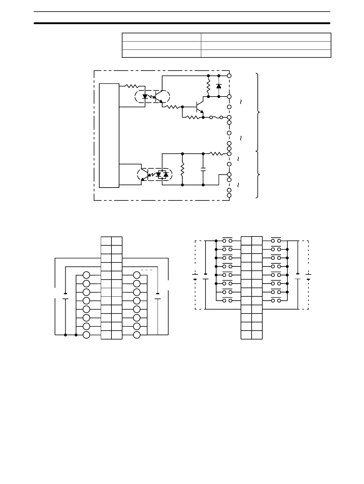
Circuit Configuration
OUT00
OUT07
COM0
OUT08
OUT15
COM1
COM2
IN08
IN15
COM3
IN00
IN07
Internal
Circuit
Fuse
4.7 kW
2.7 kW
CN1
4.5 to
26.4 VDC
4.5 to
26.4 VDC
CN2
1000 pF
620 W
Terminal Connections
I/O word “n”
CN1
I/O word “n+1”
CN2
AB
0
1
1
2
2
3
3
4
4
5
5
6
6
7
7
8
COM2
9
8
9
10
11
12
13
14
15
COM3
+
+
NC
10
NC
11
NC
NC
NC
12
NC
+
12 VDC
1
2
3
4
5
6
7
8
9
10
11
12
+
12 VDC
L
+5 to 24 VDC +5 to 24 VDC
B
1
2
3
4
5
6
7
8
9
0
1
2
3
4
5
6
7
COM0
+
10
NC
11
NC
8
9
10
11
12
13
14
15
COM1
+
NC
12
A
1
2
3
4
5
6
7
8
9
10
11
12
NC
5 to 24
VDC
5 to 24
VDC
L
L
L
L
L
L
L
L
L
L
L
L
L
L
L
Note 1. I/O word “n” is determined by the unit number setting (n = IR 100 + 10 × unit number).
2. The Unit will have 16 static output and16 static input points when pin 1 of it’s DIP switch is OFF.
3. When pin 2 of the Unit’s DIP switch is ON, input points 08 to 15 in connector 2 are high-speed inputs.
General Specifications
 Loading...


