65
The output voltage of the 24-VDC output will vary with the current consumption
of the load as shown in the following table. Be sure to check the current con-
sumption and allowable voltage ranges of the devices connected before using
these terminals.
Load current on 24-VDC
output
Less than 0.3 A 0.3 A or higher
Accuracy of 24-VDC output
for lot No. 0197 or later
+17%
–11%
+10%
–11%
Accuracy of 24-VDC output
for lot No. 3187 or earlier
+10%
–20%
Note Lot numbers are as shown in the following diagram.
0 1 9 7
1997 (Rightmost digit of year)
September (Month: 1 to 9 = Jan to Sep, X/Y/Z = Oct/Nov/Dec
01 (Day: 01 to 31)
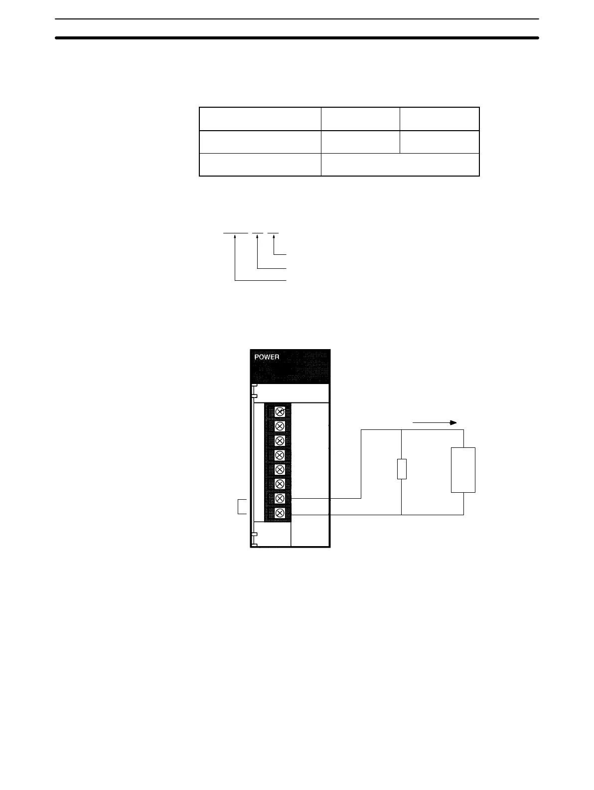
Connect a dummy load as shown in the following diagram if the maximum oper-
ating voltage of the connected device is 26.4 V (24 V +10%).
Dummy
load
Connected
device
(Photoelectric
Switch, Sen-
sor Input Unit,
etc.
24 VDC
OUTPUT
R
L
I
L
• Resistance of the dummy load:
R=24/(0.3 – I
L
) (Ω)
120 Ω when I
L
= 0.1 A
240 Ω when I
L
= 0.2 A
Not necessary when I
L
= 0.3 A
(I
L
: Total current of connected devices)
• Capacity of the dummy load resistance:
W=(0.3 – I
L
) x 26.4 x 5 (Safety factor)
30 W (120 Ω) when I
L
= 0.1 A
15 W (240 Ω) when I
L
= 0.2 A
Note Since the dummy load will generate heat, be careful not to allow any combustible
materials to come in contact with the resistor.
Wiring
Section 3-2
 Loading...


