9.2. How to Check for Errors
Checking the EtherCAT Status
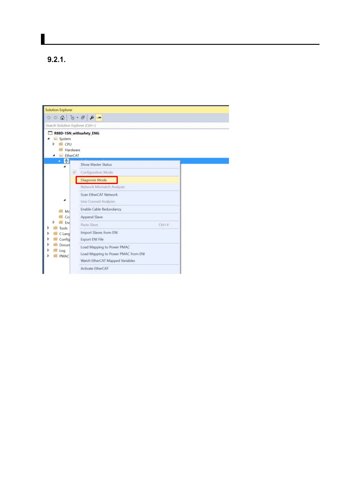
You can check the EtherCAT status from Diagnosis Mode of Power PMAC IDE.
Right-click on Master0 (Deactivated) under EtherCAT in the Solution Explorer, then select
Diagnosis Mode to open the Diagnosis Mode page
You can check the status of the slaves in the Diagnosis Mode page.
 Loading...


