92
5-3 Error Processing and Correction
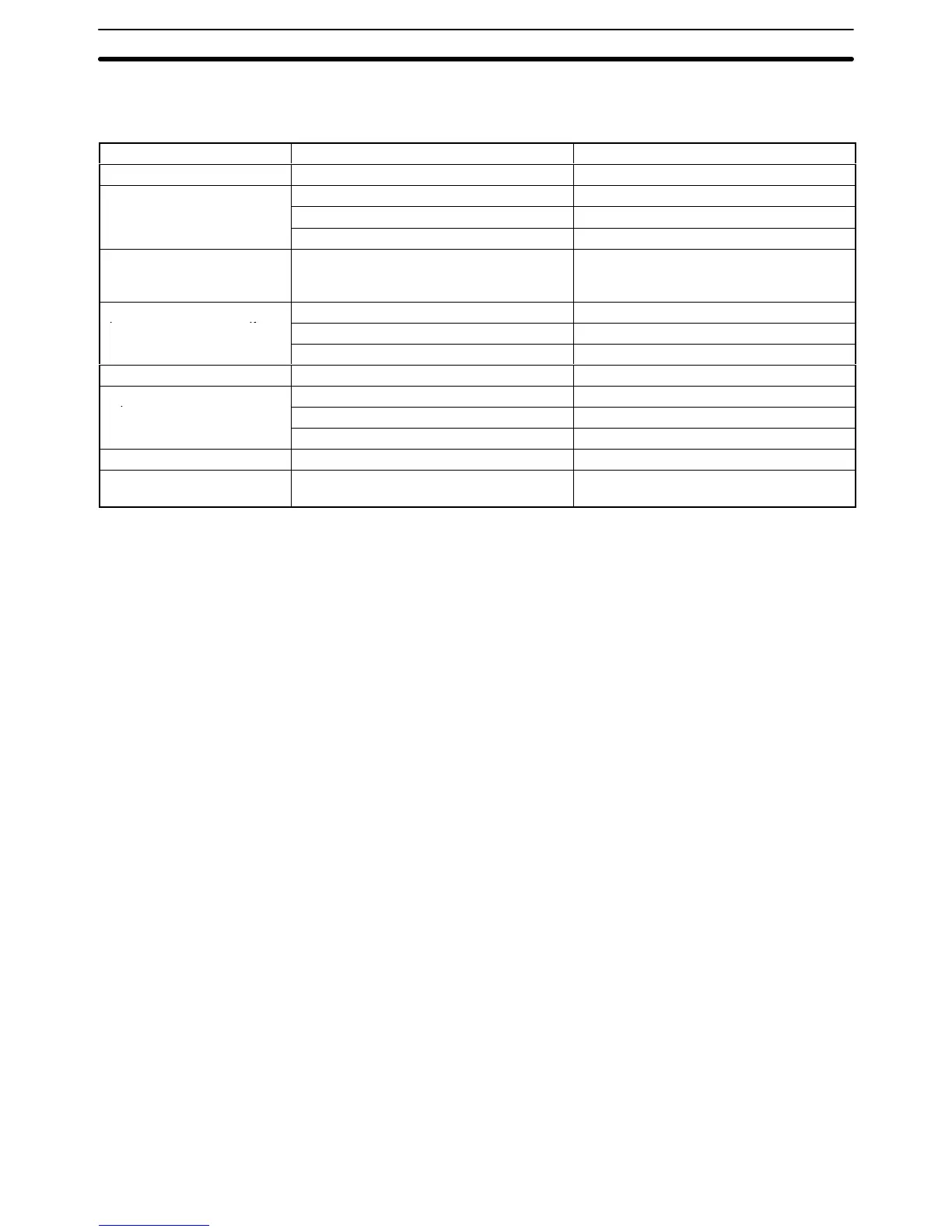
CPU Rack/Expansion CPU Rack/Expansion I/O Rack
Symptom Cause Remedy
POWER indicator is unlit. PCB short-circuited or damaged by heat. Replace Power Supply Unit or Backplane.
RUN indicator is unlit. (1) START input terminals are OFF. Short-circuit START input terminals.
(2) Error in program. Correct program
(3) Power line is faulty. Replace Power Supply Unit.
RUN output does not
turn ON.
RUN indicator lit.
Internal circuitry of
Power Supply Unit is faulty.
Replace Power Supply Unit.
Link Unit or CPU Bus Unit
(1) CPU cable is faulty. Replace CPU cable.
does not operate or malfunc-
(2) CPU bus is faulty. Replace Backplane.
t
ons.
(3) Expansion CPU Rack is faulty. Replace I/O Control or I/O Interface Unit.
Bit does not operate. I/O bus faulty. Replace Backplane.
Error occurs in units of 8
(1) I/O cable is faulty. Replace I/O cable.
points.
(2) I/O bus is faulty. Replace Backplane.
(3) Expansion I/O Rack is faulty. Replace I/O Control or I/O Interface Unit.
I/O bit turns ON I/O bus is faulty. Replace Backplane.
All bits for one Unit do not
turn ON.
I/O bus is faulty. Replace Backplane.
Error Processing and Correction Section 5-3

 Loading...


