81
5-2 Troubleshooting Flowcharts
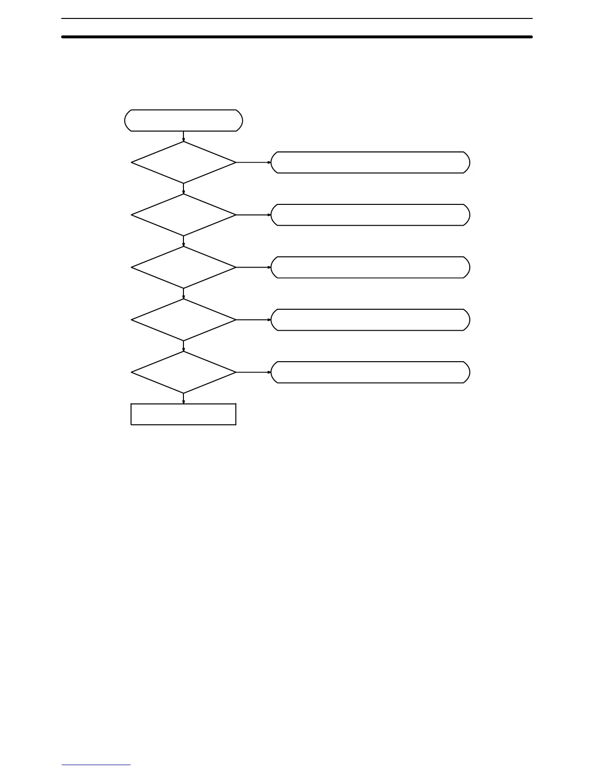
Main Flowchart When
an unknown error arises, the following troubleshooting flowchart can be
used to help locate the problem.
POWER
indicator lit?
YES
Main flowchart
See Power Check Flowchart
NO
RUN indicator lit?
YES
See Fault Check Flowchart
NO
ALARM indicator
lit?
See Error Check Flowchart
I/O sequence
correct?
YES
See I/O Check Flowchart
NO
Environment normal?
YES
See Environment Check Flowchart
NO
YES
NO
Replace Unit
Note 1. Before
replacing a Unit, be sure to turn of
f the power to the PC. The same
applies
to when replacing the Expansion Data Memory Unit, batteries, wir
-
ing, and cables.
2. When
replacing the CPU, start operation only after transferring the contents
of
the data memory or holding bits that are required for resuming operation
to the replaced CPU.
Troubleshooting Flowcharts Section 5-2

 Loading...


