72
4-3 Output Unit Fuses
The following Output Units have one fuse each as shown in the table.
Output Unit Fuse specifications
C500-OD411
C500-OD217
C500-OA223
250 V, 5 A
C500-OA121
C500-OA222
C500-OA226
250 V, 5 A
C500-OD219 250 V, 10 A
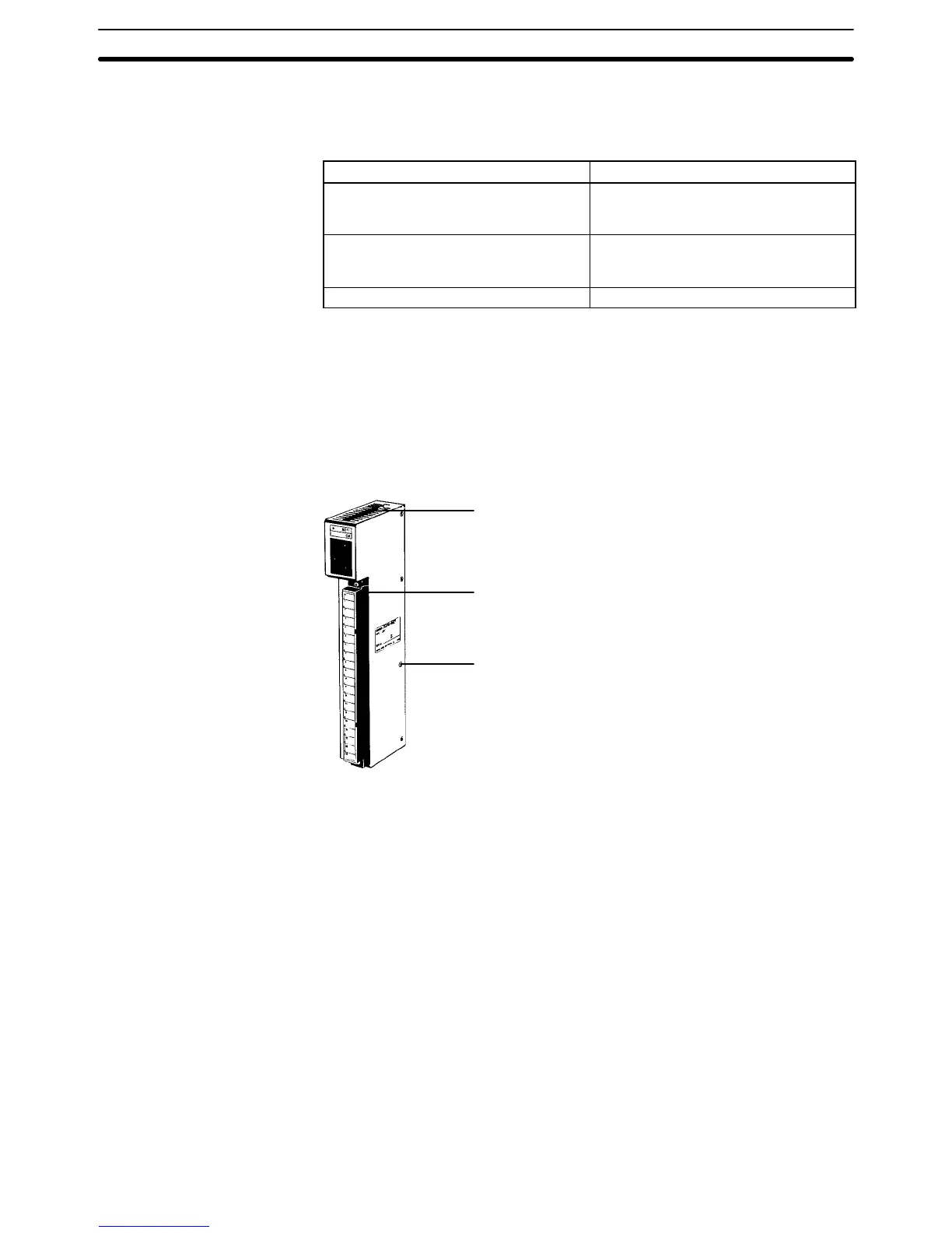
To replace a fuse in an Output Unit, perform the following steps.
1, 2, 3...
1. Turn off the power to the PC.
2. Detach
the terminal block
from the Output Unit by removing the screws lo
-
cated at the top and bottom of the terminal block.
Mounting screws
Located at the top and bottom.
Terminal block mounting screws
Located at the top and bottom of
the terminal block.
Cover mounting screws (8)
3. Remove
the screws that mount the Output Unit to the Backplane. Pulling the
Unit toward you, remove the Output Unit from the Backplane.
4. There are eight screws on each side of the Output Unit. Remove these
screws to detach the case from the cover.
5. Pull out the printed circuit board.
6. Insert a new fuse.
7. Reassemble the Unit.
4-4 Output Unit Relays
To replace a Relay in an Output Unit, take the following steps.
1, 2, 3...
1. Turn off the power to the PC.
Output Unit Relays Section 4-4

 Loading...


