94
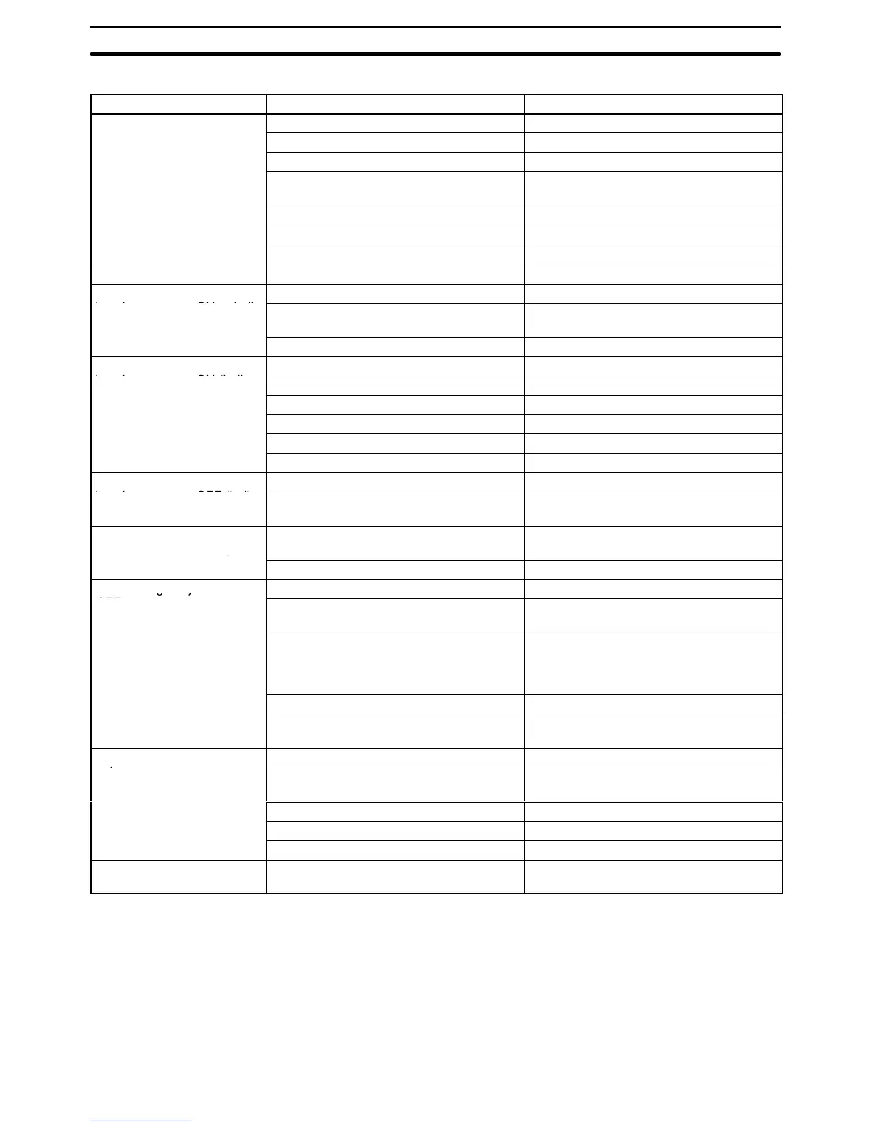
Output Units
Symptom Cause Remedy
Not all outputs turn ON (1) Load is not supplied with power. Supply power
(2) Load voltage is low. Adjust voltage to within rated range.
(3) Terminal block screws are loose. Tighten screws
(4) Faulty terminal block connector con-
tact.
Replace terminal block connector.
(5) Blown fuse Replace fuse.
(6) Faulty I/O bus connector contact. Replace Unit.
(7) Output circuit is faulty. Replace Unit.
Not all outputs turn OFF Output circuit is faulty. Replace Unit.
Output of a specific bit num-
(1) Output ON time too short. Correct program.
ber does not turn ON or indi-
cator is not lit
(2) Bit status controlled by multiple instruc-
tions.
Correct program.
(3) Faulty output circuit. Replace Unit.
Output of a specific bit num-
(1) Faulty output device. Replace output device.
ber does not turn ON (indi-
(2) Break in output wiring. Check output wiring.
cator
.
(3) Loose terminal block screws. Tighten screws.
(4) Faulty terminal block connector faulty. Replace terminal block connector.
(5) Faulty output bit. Replace relay.
(6) Faulty output circuit. Replace Unit.
Output of a specific bit num-
(1) Faulty output bit. Replace relay.
ber does not turn OFF (indi-
cator unlit).
(2) Bit does not turn OFF due to leakage
current or residual voltage.
Replace external load or add dummy resis-
tor.
Output of a specific bit num-
ber does not turn OFF (indi-
(1) Bit status controlled by multiple instruc-
tions.
Correct program.
cator lit).
(2) Faulty output circuit. Replace Unit.
Output irregularly turns ON/
(1) Low load voltage. Adjust load voltage to within rated range
OFF.
(2) Bit status controlled by multiple instruc-
tions.
Correct program
(3) Malfunction due to noise. Protective measures against noise:
(1) Install surge suppressor.
(2) Install insulation transformer.
(3) Use shielded cable.
(4) Terminal block screws are loose. Tighten screws.
(5) Faulty terminal block connector con-
tact.
Replace terminal block connector.
Error occurs in units of 8
(1) Loose common terminal screw. Tighten screws.
points.
(2) Faulty terminal block connector con-
tact.
Replace terminal block connector.
(3) Blown fuse. Replace fuse.
(4) Faulty data bus. Replace Unit.
(5) Faulty CPU. Replace CPU.
Output indicator is not lit (op-
eration is normal).
Faulty indicator. Replace Unit.
Error Processing and Correction Section 5-3

 Loading...


